GMC Yukon 2000–2006
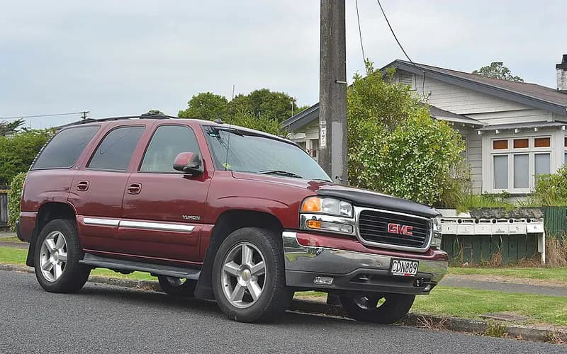
Common on this vehicle:Warning lightMisfire or rough idleLeakNoiseGauge or instrument faultDoes not startHard start or long crankLoss of engine power, no acceleration
Record by record
149 records state a cause or a remedy. Each record is shown as short labels in the order fault → finding the cause → correction. Press a label to narrow to the records that state it.
Symptom
Component named as the cause
Work done
How it is said to have ended
- says it held for a while3
- says it came back4
- says it did not fix it4
- result not stated1
A ribbon is as wide as the records that state both of its ends (only the commonest are drawn). A record that names several symptoms or components runs through each. Orange is records that say the fault came back or was not fixed. Results come from owners’ reports only; one that does not say is “result not stated”. None of this is a likelihood of a cause or a rate at which work succeeds.
Read the records one by one (22)
Known issuesCastech cylinder head porosity crack (gradual coolant loss)2
Owner complaint2004 GMC YUKON ・ 2013-09-03
Slug buildup, oil pressure loss, and coolant loss
1Fault
2Finding the cause
3Correction
Read the sentences of the record
- Fault
- MY CAR BEGAN TO HAVE A BUILD UP OF SLUGS AND BEGAN LOOSING OIL PRESSURE AND COOLANT AND NEEDED OIL ADDED AND COOLANT FREQUENTLY.
- Cause
- I WAS ADVISED TO CHANGE THE OIL FREQUENTLY TO CLEAN THE SLUG OUT BUT IT CONTINUED TO BUILD UP AND THE MYSTERY OF LOOSING COOLANT OIL PRESSURE HAS BOTTOMED OUT TWO MORE TIMES AND I FOUND A ARTICLE ON THE INTERNET THAT A NUMBER OF GMC VEHICLES INCLUDING MINE WERE BUILT WITH DEFECTIVE CYLINDER HEADS DUE TO CRACKS OVER TIME WHICH ALLOWS COOLANT TO LEAK INTO ENGINE AND MIX WITH THE OIL WHICH BUILDS UP SLUG.
- Remedy
- THE SLUGS WERE CLEANED AND A NEW OIL PUMP WAS PLACED BECAUSE OF THE BUILD UP OF SLUGS.
Manufacturer communication2001–2006 GMC YUKON DENALI ・ 2024-03-19
Internal Coolant Leak from Cylinder Head Location
1Fault
- Some vehicles may experience a gradual coolant loss over time.
2Finding the cause
Possible causes
- A very low percentage of cylinder heads manufactured with an embossed Castech logo may develop a porosity crack in a very specific area.
Steps to confirm (in the document’s order)
- Check whether the head is a Castech casting by looking for the casting logo on top of the intake port, under the rocker arm support rail and in the spring deck cavity portion of the cylinder head.
- If the head is a Castech casting, inspect the area around the five oil drain holes for witness marks indicating coolant seepage over time.
- The crack can be in any of the five cylinder head oil drains and shows as a clean or shiny area on an otherwise stained surface.
- Pressurizing the cooling system at this time may reveal coolant, air, or a combination weeping in the described area.
3Correction
Repair
- If inspection reveals evidence of coolant witness marks, replace the entire cylinder head assembly.
Caution
- If the cylinder heads are not a Castech casting, follow normal diagnostic procedures in SI to determine the cause of the coolant loss.
- If no evidence of coolant loss is found on inspection of Castech casting cylinder heads, follow normal diagnostic procedures in SI to determine the cause of the coolant loss.
Read the sentences of the record
From the manufacturer’s document
- Applies to:Applies to 2001-2006 GMC Envoy, Jimmy, Sierra and Yukon models, among other listed GM models, with the 4.8L, 5.3L or 5.7L VORTEC GEN III, GEN IV V8 engine.
- Condition:Some vehicles may experience a gradual coolant loss over time.
- Cause:A very low percentage of cylinder heads manufactured with an embossed Castech logo may develop a porosity crack in a very specific area.
- Confirm:Check whether the head is a Castech casting by looking for the casting logo on top of the intake port, under the rocker arm support rail and in the spring deck cavity portion of the cylinder head.
- Confirm:If the head is a Castech casting, inspect the area around the five oil drain holes for witness marks indicating coolant seepage over time.
- Confirm:The crack can be in any of the five cylinder head oil drains and shows as a clean or shiny area on an otherwise stained surface.
- Confirm:Pressurizing the cooling system at this time may reveal coolant, air, or a combination weeping in the described area.
- Repair:If inspection reveals evidence of coolant witness marks, replace the entire cylinder head assembly.
- Caution:If the cylinder heads are not a Castech casting, follow normal diagnostic procedures in SI to determine the cause of the coolant loss.
- Caution:If no evidence of coolant loss is found on inspection of Castech casting cylinder heads, follow normal diagnostic procedures in SI to determine the cause of the coolant loss.
Open the manufacturer’s document (PDF) ↗ The points above were read from this document.
- Remedy
- This bulletin advises the technician of possible location of an internal coolant leak from a specific cylinder head and location.
Known issuesSingle-cylinder misfire (P0300-P0308) and/or chirp, squeak or tick at camshaft speed: worn cam lobe / lifter, valve or valve spring1
Manufacturer communication2002–2006 GMC YUKON DENALI ・ 2023-05-06(1 earlier editions of this document folded here)
Diagnostic tip: valve, lifter or camshaft issue
1Fault
- Misfire, chirp, squeak, squeal or tick noise, or MIL illuminated.
- DTCs P0300 (engine misfire detected) and P0301 through P0308 (misfire detected on cylinders 1 through 8) are listed.
2Finding the cause
Possible causes
- Possible causes: worn camshaft lobe and/or lifter roller, a sticking valve, valve leakage, a broken valve spring, or a collapsed AFM lifter.
Steps to confirm (in the document’s order)
- A verified noise is not eliminated by canceling fuel injectors and occurs at camshaft speed (half of crankshaft speed).
- If applying pressure to the valve side of the rocker changes the noise, a lifter and/or cam lobe concern on that cylinder is most likely.
- Disconnect the coils and injectors on one bank, run the engine with that valve cover removed, back off the rocker arm a couple of turns and listen for a change in the noise.
- Measure cam lobe lift at the pushrod side of the rocker arm and compare with other rockers on the same bank; the misfiring or ticking cylinder should have clearly less lift.
- A good indicator of a sticking valve is misfires that keep counting on an aggressive deceleration with engine braking.
3Correction
Repair
- If a worn camshaft lobe or lifter roller is found, replace the camshaft and all lifters, and the plastic lifter guide for the affected lifter.
Caution
- A damaged cam lobe is easy to overlook through the lifter bores, and unworn lifter rollers do not mean the cam lobes are okay; inspect both carefully.
Read the sentences of the record
From the manufacturer’s document
- Applies to:Applies to GM passenger cars and trucks, 2002 through 2023, with V6/V8 pushrod engines.
- Condition:Misfire, chirp, squeak, squeal or tick noise, or MIL illuminated.
- Condition:DTCs P0300 (engine misfire detected) and P0301 through P0308 (misfire detected on cylinders 1 through 8) are listed.
- Confirm:A verified noise is not eliminated by canceling fuel injectors and occurs at camshaft speed (half of crankshaft speed).
- Cause:Possible causes: worn camshaft lobe and/or lifter roller, a sticking valve, valve leakage, a broken valve spring, or a collapsed AFM lifter.
- Confirm:If applying pressure to the valve side of the rocker changes the noise, a lifter and/or cam lobe concern on that cylinder is most likely.
- Confirm:Disconnect the coils and injectors on one bank, run the engine with that valve cover removed, back off the rocker arm a couple of turns and listen for a change in the noise.
- Confirm:Measure cam lobe lift at the pushrod side of the rocker arm and compare with other rockers on the same bank; the misfiring or ticking cylinder should have clearly less lift.
- Caution:A damaged cam lobe is easy to overlook through the lifter bores, and unworn lifter rollers do not mean the cam lobes are okay; inspect both carefully.
- Repair:If a worn camshaft lobe or lifter roller is found, replace the camshaft and all lifters, and the plastic lifter guide for the affected lifter.
- Confirm:A good indicator of a sticking valve is misfires that keep counting on an aggressive deceleration with engine braking.
- Confirm:A broken valve spring may stay stacked together and be hard to see; lightly push on different places on the springs with a small hammer handle.
Open the manufacturer’s document (PDF) ↗ The points above were read from this document.
- Remedy
- This diagnostic tip bulletin provides additional information on how to diagnose a possible valve, lifter or camshaft issue.
Known issuesReduced Engine Power from throttle body connector crimp, broken wire or grounds1
Owner complaint2004 GMC YUKON DENALI ・ 2013-03-03
Stability control disabled and reduced engine power warnings with 5 MPH speed limit on startup
1Fault
2Finding the cause
Not stated
3Correction
Read the sentences of the record
- Fault
- THE "STABILITY CONTROL DISABLED" SENSOR COMES ON FOLLOWED BY "REDUCED ENGINE POWER" AND MY VEHICLE WON'T GO FASTER THAN 5MPH (= 8.05 km/h). (1 more)
- Remedy
- THEY REPLACED THE "CONNECTOR AT THE THROTTLE BODY" AND CHARGED ME $223.09. (1 more)
- Outcome
- THE ISSUE TEMPORARILY WENT AWAY.
ENGINE AND ENGINE COOLING11
Manufacturer communication2000–2006 GMC YUKON DENALI ・ 2024-02-29(2 earlier editions of this document folded here)
Oil Cooler, Oil Cooler Lines, and Oil Tank Replacement Service Information
1Fault
Not stated
2Finding the cause
Possible causes
- Debris from a damaged rod or main bearing is sent directly through the oil galleries and the components in the lubrication circuit.
3Correction
Repair
- Whenever an engine assembly is replaced for a connecting rod or crankshaft main bearing failure, also replace the oil cooler, oil cooler lines, oil tank and turbocharger, if equipped.
- If the oil cooler is part of the radiator assembly, the radiator must be replaced along with the other required components.
Caution
- Reinstalling an oil cooler or cooler line from an engine with bearing failure debris may carry remaining debris into the new service engine.
- Some service engines come with the oil cooler and/or oil cooler lines already attached; those need not be replaced.
- Not every engine with bearing damage requires the oil cooler, lines or oil tank, or even the engine, to be replaced.
Read the sentences of the record
From the manufacturer’s document
- Applies to:Applies to all GM passenger cars and trucks, 2000 through 2024, gasoline engines only.
- Repair:Whenever an engine assembly is replaced for a connecting rod or crankshaft main bearing failure, also replace the oil cooler, oil cooler lines, oil tank and turbocharger, if equipped.
- Repair:If the oil cooler is part of the radiator assembly, the radiator must be replaced along with the other required components.
- Cause:Debris from a damaged rod or main bearing is sent directly through the oil galleries and the components in the lubrication circuit.
- Caution:Reinstalling an oil cooler or cooler line from an engine with bearing failure debris may carry remaining debris into the new service engine.
- Caution:Some service engines come with the oil cooler and/or oil cooler lines already attached; those need not be replaced.
- Caution:Not every engine with bearing damage requires the oil cooler, lines or oil tank, or even the engine, to be replaced.
Open the manufacturer’s document (PDF) ↗ The points above were read from this document.
- Remedy
- This service bulletin provides service information to technicians on guidelines to replace Oil Cooler, Oil Cooler Lines and Oil Tank if the engine was replaced where large amounts of debris has flowed throughout the oiling system.
Manufacturer communication2000–2006 GMC YUKON DENALI ・ 2024-02-02
1Fault
Not stated
2Finding the cause
Steps to confirm (in the document’s order)
- Refer to the Engine Mechanical Specification in SI for the correct bore and piston specification.
3Correction
Repair
- When installing a piston into a cylinder, use a ring compressor sleeve or equivalent for best results.
- Choose a sleeve with a smooth radius that tapers down to the specific bore size.
- Select a size only slightly bigger than the piston diameter and not larger than the cylinder bore diameter.
Caution
- If a sleeve is unavailable in the needed size, a universal ring compressor will work but is more difficult to use.
Read the sentences of the record
From the manufacturer’s document
- Applies to:Applies to 2024 and earlier GM passenger cars and trucks.
- Repair:When installing a piston into a cylinder, use a ring compressor sleeve or equivalent for best results.
- Repair:Choose a sleeve with a smooth radius that tapers down to the specific bore size.
- Repair:Select a size only slightly bigger than the piston diameter and not larger than the cylinder bore diameter.
- Confirm:Refer to the Engine Mechanical Specification in SI for the correct bore and piston specification.
- Caution:If a sleeve is unavailable in the needed size, a universal ring compressor will work but is more difficult to use.
Open the manufacturer’s document (PDF) ↗ The points above were read from this document.
- Remedy
- This PI bulletin advises the technician on the proper way to install the pistons in an engine.
Manufacturer communication2001–2005 GMC YUKON DENALI ・ 2023-12-11
Expanded Availability for Remanufactured Electronic Control Modules
1Fault
Not stated
2Finding the cause
Not stated
3Correction
Expanded Availability for Remanufacture and Return (R&R) Electronic Control Modules
Read the sentences of the record
- Remedy
- Expanded Availability for Remanufacture and Return (R&R) Electronic Control Modules
Manufacturer communication2004–2006 GMC YUKON DENALI ・ 2023-11-22
Vibration Analysis Worksheet Service Bulletin
1Fault
2Finding the cause
Steps to confirm (in the document’s order)
- When diagnosing vibration, use the worksheet together with the Vibration Analysis - Road Testing procedure in the service information.
- Place the sensor where the vibration is felt: on the seat track for a seat complaint, on the steering column for a steering wheel complaint.
- Moving the sensor to other areas, look for the same Hz reading with the greatest amplitude.
- If a system balance was attempted and the vibration remains, check ring gear backlash at each tooth; readings should not vary more than 0.050 mm (0.002 in).
- Aluminum wheel/tire runout measured on the vehicle: maximum 0.030 in (.762 mm).
3Correction
Read the sentences of the record
From the manufacturer’s document
- Applies to:Applies to 2024 and prior GM passenger cars and trucks.
- Confirm:When diagnosing vibration, use the worksheet together with the Vibration Analysis - Road Testing procedure in the service information.
- Confirm:Place the sensor where the vibration is felt: on the seat track for a seat complaint, on the steering column for a steering wheel complaint.
- Confirm:Moving the sensor to other areas, look for the same Hz reading with the greatest amplitude.
- Confirm:If a system balance was attempted and the vibration remains, check ring gear backlash at each tooth; readings should not vary more than 0.050 mm (0.002 in).
- Confirm:Aluminum wheel/tire runout measured on the vehicle: maximum 0.030 in (.762 mm).
- Confirm:Hub mounting surface runout: maximum 0.005 in (0.132 mm).
- Confirm:Wheel stud runout: maximum 0.010 in (0.254 mm).
Open the manufacturer’s document (PDF) ↗ The points above were read from this document.
- Remedy
- This service bulletin provides a vibration analysis worksheet the technician can use in conjunction with the appropriate Vibration Analysis-Road testing procedure when diagnosing vibration concerns.
Manufacturer communication2000–2006 GMC YUKON DENALI ・ 2023-09-26
Normal Transmission Shift and Throttle Response Delay
1Fault
- A sag or hesitation may be noticed when coasting at low speeds of less than 24 km/h (15 mph) with a closed throttle and then aggressively applying the throttle.
- With an automatic transmission, after a hard complete stop with a closed throttle immediately followed by an aggressive throttle opening, the downshifts may not be completed by the time the throttle is opened.
- A sag or hesitation may also be noticed while cruising at highway speeds and then aggressively increasing the throttle, forcing a down-shift.
2Finding the cause
Possible causes
- In this maneuver the throttle blade is opened slowly for up to 0.7 seconds, even though the accelerator is applied aggressively, to help minimize driveline lash and clunking.
- As a result, approximately 0.5 seconds of zero torque may be commanded to allow the shift to first gear to occur.
3Correction
Caution
- All of these conditions are a result of Torque Management and should be considered normal; no repairs should be attempted.
Read the sentences of the record
From the manufacturer’s document
- Applies to:GM passenger cars and trucks, model years 2000 to 2024.
- Condition:A sag or hesitation may be noticed when coasting at low speeds of less than 24 km/h (15 mph) with a closed throttle and then aggressively applying the throttle.
- Cause:In this maneuver the throttle blade is opened slowly for up to 0.7 seconds, even though the accelerator is applied aggressively, to help minimize driveline lash and clunking.
- Condition:With an automatic transmission, after a hard complete stop with a closed throttle immediately followed by an aggressive throttle opening, the downshifts may not be completed by the time the throttle is opened.
- Cause:As a result, approximately 0.5 seconds of zero torque may be commanded to allow the shift to first gear to occur.
- Condition:A sag or hesitation may also be noticed while cruising at highway speeds and then aggressively increasing the throttle, forcing a down-shift.
- Caution:All of these conditions are a result of Torque Management and should be considered normal; no repairs should be attempted.
Open the manufacturer’s document (PDF) ↗ The points above were read from this document.
- Remedy
- The service bulletin advises the tech of a normal transmission shift condition and the delay in throttle response when the throttle plate is opened rapidly and advises the customer that it is normal for the delay.
Manufacturer communication2000–2006 GMC YUKON DENALI ・ 2023-09-15
Engine Component Wear Service Guidelines
1Fault
- Some technicians may be replacing engines instead of repairing them and replacing worn components as needed.
2Finding the cause
Possible causes
- The wear may be caused by the vehicle duty cycle, dust in the operating environment and local fuel quality.
Steps to confirm (in the document’s order)
- Cylinder wall scratch: if a pick or fingernail cannot catch on it, the cylinder bore/engine block does not require replacement.
- With a scored piston, inspect for broken and/or stuck rings, and inspect the ring lands and cylinder wall for damage.
- When bearing failure is suspected, remove the oil filter and inspect it for excessive debris and damaged pleats.
- Minimal amounts of metal particles on the oil filter pleats should not pose a concern.
- Excessive metal particles or damaged filter pleats mean unfiltered oil with bearing debris may have been pumped into the oil galleries throughout the engine.
3Correction
Repair
- Minor scratching/scoring on camshaft lobes and/or camshaft bearing journals: the scored components can be replaced without replacing the engine assembly.
- Minor scratching/scoring on connecting rod bearings: the scored components can be replaced without replacing the engine assembly.
- A slightly scored piston can be replaced without replacing the engine assembly.
Caution
- If inspection reveals cylinder wall damage (excessive scoring or out-of-round), an engine replacement may be required.
Read the sentences of the record
From the manufacturer’s document
- Applies to:Applies to GM passenger cars and trucks, model years 2000 to 2024.
- Condition:Some technicians may be replacing engines instead of repairing them and replacing worn components as needed.
- Cause:The wear may be caused by the vehicle duty cycle, dust in the operating environment and local fuel quality.
- Repair:Minor scratching/scoring on camshaft lobes and/or camshaft bearing journals: the scored components can be replaced without replacing the engine assembly.
- Repair:Minor scratching/scoring on connecting rod bearings: the scored components can be replaced without replacing the engine assembly.
- Confirm:Cylinder wall scratch: if a pick or fingernail cannot catch on it, the cylinder bore/engine block does not require replacement.
- Repair:A slightly scored piston can be replaced without replacing the engine assembly.
- Confirm:With a scored piston, inspect for broken and/or stuck rings, and inspect the ring lands and cylinder wall for damage.
- Caution:If inspection reveals cylinder wall damage (excessive scoring or out-of-round), an engine replacement may be required.
- Confirm:When bearing failure is suspected, remove the oil filter and inspect it for excessive debris and damaged pleats.
- Confirm:Minimal amounts of metal particles on the oil filter pleats should not pose a concern.
- Confirm:Excessive metal particles or damaged filter pleats mean unfiltered oil with bearing debris may have been pumped into the oil galleries throughout the engine.
Open the manufacturer’s document (PDF) ↗ The points above were read from this document.
- Remedy
- This service bulletin provides graphics, information and guidelines for engine component wear to assist service personnel as a guideline to perform necessary engine repairs and prevent unnecessary engine replacement.
Manufacturer communication2000–2006 GMC YUKON DENALI ・ 2023-04-12(4 earlier editions of this document folded here)
ACDelco Spin-On Oil Filter Torque Specification Notification
1Fault
- An oil leak from underneath the front of the vehicle after an earlier oil service; the leak can take several thousand miles to appear.
2Finding the cause
Possible causes
- The oil may be leaking from between the oil filter gasket and the mounting surface.
Steps to confirm (in the document’s order)
- The filter may be very easy to remove, sometimes by hand.
3Correction
Repair
- Lubricate the new oil filter gasket with clean engine oil.
- Install the oil filter 1 full turn after the gasket contacts the sealing surface on the filter mounting flange.
Read the sentences of the record
From the manufacturer’s document
- Applies to:Applies to all passenger cars and trucks, model years 2000 to 2024.
- Condition:An oil leak from underneath the front of the vehicle after an earlier oil service; the leak can take several thousand miles to appear.
- Cause:The oil may be leaking from between the oil filter gasket and the mounting surface.
- Confirm:The filter may be very easy to remove, sometimes by hand.
- Repair:Lubricate the new oil filter gasket with clean engine oil.
- Repair:Install the oil filter 1 full turn after the gasket contacts the sealing surface on the filter mounting flange.
Open the manufacturer’s document (PDF) ↗ The points above were read from this document.
- Remedy
- This service bulletin provides service information on new torque specification and installation procedure for ACDelco Spin-On Oil Filters.
Manufacturer communication2000–2006 GMC YUKON DENALI ・ 2023-01-06
EVAP Leak Diagnostic Service Bulletin (DTCs P0442/P0455)
1Fault
- The MIL is illuminated, and DTC P0442 (EVAP small leak detected) and/or P0455 (EVAP large leak detected) may be set in the ECM.
2Finding the cause
Possible causes
- P0455 sets because of a large leak or a purge blockage: an unseated tube connection, a damaged tube, a canister vent valve stuck open, or a purge valve stuck closed.
- P0442 sets because of a small leak, which can come from a purge valve stuck open or a canister vent valve stuck open.
Steps to confirm (in the document’s order)
- Inspect every purge connection for proper installation, and look along the lines for damage or wear; if damage is seen, confirm it with the smoke test.
- Some leaks show only under pressure and some only under vacuum, so check both ways; cycling the purge and vent solenoids with GDS2 while inspecting may show a sticking valve.
- Critical connections to check include: purge tube to purge valve (at the intake manifold), purge tube to chassis EVAP line (rear of the engine, near the transmission), chassis EVAP line to canister, and fuel tank load line to canister.
- Also check the vent valve line at the vent valve, the fuel tank load line jumper connection near the fuel tank, and that the fuel tank cap is closed properly.
- If all connections are good, check the vent valve for a stuck-open position; if the vent valve works correctly, go on to the purge valve.
3Correction
Parts
- No parts are required for this repair.
Caution
- For diagnostic instructions, DTC information and required tools, always follow the service information document for the vehicle and DTC being worked on.
Read the sentences of the record
From the manufacturer’s document
- Applies to:This bulletin only applies to vehicles with gasoline engines.
- Condition:The MIL is illuminated, and DTC P0442 (EVAP small leak detected) and/or P0455 (EVAP large leak detected) may be set in the ECM.
- Cause:P0455 sets because of a large leak or a purge blockage: an unseated tube connection, a damaged tube, a canister vent valve stuck open, or a purge valve stuck closed.
- Cause:P0442 sets because of a small leak, which can come from a purge valve stuck open or a canister vent valve stuck open.
- Confirm:Inspect every purge connection for proper installation, and look along the lines for damage or wear; if damage is seen, confirm it with the smoke test.
- Confirm:Some leaks show only under pressure and some only under vacuum, so check both ways; cycling the purge and vent solenoids with GDS2 while inspecting may show a sticking valve.
- Confirm:Critical connections to check include: purge tube to purge valve (at the intake manifold), purge tube to chassis EVAP line (rear of the engine, near the transmission), chassis EVAP line to canister, and fuel tank load line to canister.
- Confirm:Also check the vent valve line at the vent valve, the fuel tank load line jumper connection near the fuel tank, and that the fuel tank cap is closed properly.
- Confirm:If all connections are good, check the vent valve for a stuck-open position; if the vent valve works correctly, go on to the purge valve.
- Confirm:Work in this order: EVAP lines properly installed and fully seated; damage on the EVAP lines; vent valve malfunction; purge valve malfunction.
- Parts:No parts are required for this repair.
- Caution:For diagnostic instructions, DTC information and required tools, always follow the service information document for the vehicle and DTC being worked on.
Open the manufacturer’s document (PDF) ↗ The points above were read from this document.
- Remedy
- This service bulletin provides diagnostic tips/steps on testing for possible EVAP leaks in the system to correct a customer concern of an MIL Illuminated with DTCs P0442 and/or P0455 Set.
Manufacturer communication2003–2006 GMC YUKON DENALI ・ 2022-10-11(1 earlier editions of this document folded here)
OEM and Remanufactured Engine/Transmission ID Notification
1Fault
Not stated
2Finding the cause
Steps to confirm (in the document’s order)
- The engine bar code tag could be on a rocker arm cover, on the ends of a cylinder head, or on the oil pan or oil rail area of the engine.
- All remanufactured engines have a label on the right or left side of the block.
- On the 4.8L/5.3L/6.0L/6.2L (Gen III/Gen IV) engines the remanufactured engine label is on the left side of the block.
3Correction
Caution
- If a piston must be replaced, measure the cylinder before ordering; most of these engines have oversized cylinders, and oversized piston ring packs are not available for service.
- If crankshaft bearings must be replaced, measure the crankshaft before ordering; a crankshaft that has been turned must be replaced, together with all new standard size bearings.
Read the sentences of the record
From the manufacturer’s document
- Applies to:Applies to 2003–2023 GM passenger cars and trucks.
- Confirm:The engine bar code tag could be on a rocker arm cover, on the ends of a cylinder head, or on the oil pan or oil rail area of the engine.
- Confirm:All remanufactured engines have a label on the right or left side of the block.
- Confirm:On the 4.8L/5.3L/6.0L/6.2L (Gen III/Gen IV) engines the remanufactured engine label is on the left side of the block.
- Caution:If a piston must be replaced, measure the cylinder before ordering; most of these engines have oversized cylinders, and oversized piston ring packs are not available for service.
- Caution:If crankshaft bearings must be replaced, measure the crankshaft before ordering; a crankshaft that has been turned must be replaced, together with all new standard size bearings.
Open the manufacturer’s document (PDF) ↗ The points above were read from this document.
- Remedy
- This service bulletin provides information on OEM and Remanufactured Engine and Automatic Transmission/Transaxle Identification.
Manufacturer communication2000–2006 GMC YUKON DENALI ・ 2022-09-07
MIL Illuminated with Fuel Trim and Oxygen Sensor Codes
1Fault
- Leak
- Warning light
- P0101
- P0137 (general documents only)
- P0138 (general documents only)
- P0140 (general documents only)
- P0141
- P0157 (general documents only)
- Customers may comment that the MIL is illuminated.
- Initial diagnosis may show fuel trim and O2 sensor related codes including P0101, P0137, P0138, P0140, P0141, P0157, P0158, P0160 and P0161.
- The listed codes also include P0171, P0174, P0420, P0430, P1174 and P1175.
2Finding the cause
Possible causes
- These methods find small leaks around the O2 sensor embossments and slight cracks in an intake plenum or gasket.
Steps to confirm (in the document’s order)
- If normal SI diagnostics do not lead to a resolution and an intake vacuum leak or exhaust leak is suspected, use the GE-52250 Variable Pressure Leak Detector (preferred), the J-41416 ultrasonic leak tester, or possibly soapy water with low pressure air into the tailpipe to find the leak.
- For an intake leak, introduce the smoke into the brake booster hose or the oil dipstick tube; soapy water can be sprayed near the gasket, seams and all vacuum nipples.
- For an exhaust leak, put the hose with smoke or air into the tailpipe sealed with shop towels, then spray soapy water around seals, seams and bosses.
3Correction
Parts
- No parts are required for this repair.
Caution
- All of these tests are much more effective if the throttle body is covered or sealed.
Read the sentences of the record
From the manufacturer’s document
- Applies to:Applies to Buick, Cadillac, Chevrolet and GMC passenger cars and trucks, model years 2000 to 2022, gasoline engines only.
- Condition:Customers may comment that the MIL is illuminated.
- Condition:Initial diagnosis may show fuel trim and O2 sensor related codes including P0101, P0137, P0138, P0140, P0141, P0157, P0158, P0160 and P0161.
- Condition:The listed codes also include P0171, P0174, P0420, P0430, P1174 and P1175.
- Confirm:If normal SI diagnostics do not lead to a resolution and an intake vacuum leak or exhaust leak is suspected, use the GE-52250 Variable Pressure Leak Detector (preferred), the J-41416 ultrasonic leak tester, or possibly soapy water with low pressure air into the tailpipe to find the leak.
- Caution:All of these tests are much more effective if the throttle body is covered or sealed.
- Confirm:For an intake leak, introduce the smoke into the brake booster hose or the oil dipstick tube; soapy water can be sprayed near the gasket, seams and all vacuum nipples.
- Confirm:For an exhaust leak, put the hose with smoke or air into the tailpipe sealed with shop towels, then spray soapy water around seals, seams and bosses.
- Cause:These methods find small leaks around the O2 sensor embossments and slight cracks in an intake plenum or gasket.
- Parts:No parts are required for this repair.
Open the manufacturer’s document (PDF) ↗ The points above were read from this document.
- Remedy
- This bulletin provides information on tools available to find an intake vacuum leak or exhaust leak to correct a condition of MIL Illuminated with Multiple Fuel Trim and/or Oxygen Sensor Codes Set.
Manufacturer communication2000–2006 GMC YUKON DENALI ・ 2021-04-19
Induction System Icing Inspection in Cold Ambient Temperatures
1Fault
- The check engine light comes on and engine performance is poor in very cold ambient temperatures.
2Finding the cause
Not stated
3Correction
Read the sentences of the record
From the manufacturer’s document
- Applies to:Vehicles equipped with turbocharged gasoline engines, which may set DTC P0299 or P2227.
- Condition:The check engine light comes on and engine performance is poor in very cold ambient temperatures.
Open the manufacturer’s document (PDF) ↗ The points above were read from this document.
- Remedy
- This Preliminary information communicates to the technician the need to inspect the induction system for potential icing issues in very cold ambient temperatures. To allow the ice to melt so that it can be drained from the related components. That any of the listed DTC's may set with or without poor engine performance. Â
ENGINE5
Manufacturer communication2000–2006 GMC YUKON DENALI ・ 2024-07-16(2 earlier editions of this document folded here)
Fuel Injection Cleaner Kit Service Bulletin
1Fault
- Hard start or long crank
- Misfire or rough idle
- Does not start
- Warning light
- Check engine / Service Engine Soon
- P0300
- P0301
- P0302
- P0303
- P0304
- P0305
- Rough idle, crank no start, extended crank or misfire, with the engine warning lamp on and DTC P0300, P0301, P0302, P0303, P0304, P0305, P0306, P0307 or P0308 set.
- When the engine is cold, compression on multiple cylinders may be zero.
- The engine may pop through the intake or exhaust while cranking, and the spark plugs may be fuel fouled.
2Finding the cause
Possible causes
- Major carbon build-up on the intake and/or exhaust valves from fuel contamination or incomplete burning of the fuel; misfires should not appear before at least 8,000 km (5,000 mi).
3Correction
Repair
- If there is no valve damage and no cam follower out of place, perform the cleaning procedure to free sticking valves and remove carbon from the valves and pistons.
- If valves are damaged or cam followers are out of place, make the engine mechanical repairs first and then perform the cleaning procedure to prevent a return.
- Fill Cleaner Kit J-35800-A with about 650 ml (22 oz, 2 cans) of Air Intake, Combustion Chamber Cleaner and set the air pressure at the tool to 260 kPa (40 psi).
- With GDS 2 or a scan tool, command engine idle to 2000 rpm so the engine does not stall.
- With the engine at operating temperature in a well-ventilated area, slowly and carefully induce the cleaner into the engine, taking about 3 minutes.
Parts
- The Top Engine Cleaning Kit (ACDelco Air Intake, Valve and Combustion Chamber Cleaner and ACDelco Fuel System Cleaner 44K) is 19435372 for the U.S. and Canada.
Part numbers printed in the document
19435372MAINTENANCE KIT,FUEL SYSTEM ACDELCO 3-11OZLook up at RockAuto (aftermarket candidates) ↗Search the web ↗
No successor statedas stated by GMPartsGiant (checked 2026-10-06) ↗
The numbers are as the document prints them. The name and the replacing number are what the pages of GMPartsGiant, a reseller of genuine parts and not GM, state. Aftermarket equivalents are not checked here (the links only search by number). Confirm the fit for the vehicle (VIN) before ordering.
Caution
- Inducing too much cleaner at too low an RPM, or stalling the engine with too much cleaner at once, may hydro-lock the engine and bend a connecting rod.
Read the sentences of the record
From the manufacturer’s document
- Applies to:Applies to GM passenger cars and trucks with gasoline engines only, model years 2000 to 2025.
- Condition:Rough idle, crank no start, extended crank or misfire, with the engine warning lamp on and DTC P0300, P0301, P0302, P0303, P0304, P0305, P0306, P0307 or P0308 set.
- Condition:When the engine is cold, compression on multiple cylinders may be zero.
- Condition:The engine may pop through the intake or exhaust while cranking, and the spark plugs may be fuel fouled.
- Cause:Major carbon build-up on the intake and/or exhaust valves from fuel contamination or incomplete burning of the fuel; misfires should not appear before at least 8,000 km (5,000 mi).
- Repair:If there is no valve damage and no cam follower out of place, perform the cleaning procedure to free sticking valves and remove carbon from the valves and pistons.
- Repair:If valves are damaged or cam followers are out of place, make the engine mechanical repairs first and then perform the cleaning procedure to prevent a return.
- Caution:Inducing too much cleaner at too low an RPM, or stalling the engine with too much cleaner at once, may hydro-lock the engine and bend a connecting rod.
- Repair:Fill Cleaner Kit J-35800-A with about 650 ml (22 oz, 2 cans) of Air Intake, Combustion Chamber Cleaner and set the air pressure at the tool to 260 kPa (40 psi).
- Repair:With GDS 2 or a scan tool, command engine idle to 2000 rpm so the engine does not stall.
- Repair:With the engine at operating temperature in a well-ventilated area, slowly and carefully induce the cleaner into the engine, taking about 3 minutes.
- Parts:The Top Engine Cleaning Kit (ACDelco Air Intake, Valve and Combustion Chamber Cleaner and ACDelco Fuel System Cleaner 44K) is 19435372 for the U.S. and Canada.
Open the manufacturer’s document (PDF) ↗ The points above were read from this document.
- Remedy
- This service bulletin advises of a new fuel injection cleaner kit used for decarbonizing the intake valves to correct conditions of rough idle, Crank no start, extended crank or misfire, MIL with DTCs, and explains how Top Tier fuels should be used to reduce carbon build-up.
Manufacturer communication2000–2006 GMC YUKON ・ 2023-09-18(4 earlier editions of this document folded here)
Misfire and DTC Codes Diagnostic Information
1Fault
- With DTC P0300 - P0308 and/or P050D, use GDS and save the freeze frame records.
2Finding the cause
Steps to confirm (in the document’s order)
- Perform the relative compression test in the PICO NVH or Oscilloscope software; SI Document number 5518386 covers the procedure.
- If it passes the relative compression test, the concern is an ignition or fuel delivery issue.
- Check the ignition supply voltage to the ignition module/coil assemblies and also to the fuel injectors.
- Inspect the spark plugs for anything abnormal.
- Note the fuel trim values and on which bank, and compare actual MAF with calculated air flow.
3Correction
Caution
- The injector balance procedure in GDS is only a preliminary test and its results should not decide injector replacement, especially with a low or no flow injector.
Read the sentences of the record
From the manufacturer’s document
- Applies to:All brands and models with gas engines, model years 2000 - 2024.
- Condition:With DTC P0300 - P0308 and/or P050D, use GDS and save the freeze frame records.
- Confirm:Perform the relative compression test in the PICO NVH or Oscilloscope software; SI Document number 5518386 covers the procedure.
- Confirm:If it passes the relative compression test, the concern is an ignition or fuel delivery issue.
- Confirm:Check the ignition supply voltage to the ignition module/coil assemblies and also to the fuel injectors.
- Confirm:Inspect the spark plugs for anything abnormal.
- Caution:The injector balance procedure in GDS is only a preliminary test and its results should not decide injector replacement, especially with a low or no flow injector.
- Confirm:Note the fuel trim values and on which bank, and compare actual MAF with calculated air flow.
- Confirm:Check for a possible fuel quality issue, especially with a cold engine hard start and/or a misfire on all cylinders.
- Confirm:Confirm whether a crankshaft variation learn has been completed and whether there is any abnormal engine noise possibly related to the misfire.
Open the manufacturer’s document (PDF) ↗ The points above were read from this document.
- Remedy
- This Preliminary information communicates information that will need to be provided to TAC to aid in diagnosing if a vehicle comes in with misfire and DTC Codes P0300 - P0308 and/or P050D
Manufacturer communication2003–2006 GMC YUKON DENALI ・ 2022-05-10
Warranty Administration Guidelines for Multiple Independent Repairs
1Fault
- When one customer concern needs two or more components repaired or replaced, it can be unclear which labor codes apply to the warranty transaction.
2Finding the cause
Not stated
3Correction
Read the sentences of the record
From the manufacturer’s document
- Applies to:Applies to 2023 and prior GM passenger cars and light duty trucks.
- Condition:When one customer concern needs two or more components repaired or replaced, it can be unclear which labor codes apply to the warranty transaction.
Open the manufacturer’s document (PDF) ↗ The points above were read from this document.
- Remedy
- This service bulletin provides policy information on warranty administration guidelines for multiple repairs with independent causes (GM Canada Dealers Only).
Manufacturer communication2003–2006 GMC YUKON DENALI ・ 2021-04-20
Engine and Transmission Identification
1Fault
Not stated
2Finding the cause
Not stated
3Correction
OEM and Remanufactured Engine and Automatic Transmission/Transaxle Identification
Read the sentences of the record
- Remedy
- OEM and Remanufactured Engine and Automatic Transmission/Transaxle Identification
Manufacturer communication2000–2006 GMC YUKON DENALI ・ 2020-08-10
Needle Bearings in Roller Rockers During Oil Change
1Fault
- Needle bearings may be found in the oil pan during an oil change.
2Finding the cause
Steps to confirm (in the document’s order)
- If roller rocker arm needle bearings are found during an oil change, inspect all the roller rocker arms.
- There should be 66 bearings, 33 a side.
3Correction
Repair
- Replace only the broken roller rocker arm; the remaining roller rocker arms need not be replaced.
- Needle bearings may also be in the cylinder head oil drains; clean the oil drains to retrieve them.
Caution
- The oil pan does not need to be removed: the needle bearing is larger than the oil pump pickup screen mesh and cannot be pulled into the oil pump.
Read the sentences of the record
From the manufacturer’s document
- Applies to:Applies to all brands and models, 2000 - 2021, with V6 or V8 push rod engines with roller rockers.
- Condition:Needle bearings may be found in the oil pan during an oil change.
- Confirm:If roller rocker arm needle bearings are found during an oil change, inspect all the roller rocker arms.
- Repair:Replace only the broken roller rocker arm; the remaining roller rocker arms need not be replaced.
- Repair:Needle bearings may also be in the cylinder head oil drains; clean the oil drains to retrieve them.
- Confirm:There should be 66 bearings, 33 a side.
- Caution:The oil pan does not need to be removed: the needle bearing is larger than the oil pump pickup screen mesh and cannot be pulled into the oil pump.
Open the manufacturer’s document (PDF) ↗ The points above were read from this document.
- Remedy
- This Preliminary Information communication provides information to the technician about finding needle bearings during an oil change. Technician will gain access to the roller rockers to inspect them. Only replace the roller rocker that is missing needle bearings. Be sure to clean the oil drains to retrieve the needle bearings. Each roller rocker has 66 bearings.
ELECTRICAL SYSTEM2
Owner complaint2004 GMC YUKON ・ 2025-03-05
Power loss and shaking while driving at 45 MPH; multiple repairs unsuccessful
1Fault
2Finding the cause
3CorrectionNot repaired
Read the sentences of the record
- Fault
- The contact stated while driving 45 MPH (= 72.4 km/h), the vehicle started losing motive power. (3 more)
- Remedy
- The vehicle was not repaired for the most recent failure.
- Inspection
- The vehicle was taken to an independent mechanic where it was diagnosed with throttle body failure; however, the failure persisted.
- Outcome
- The vehicle was repaired but the failure persisted three more times with different diagnoses.
Owner complaint2004 GMC YUKON ・ 2021-06-02
Reduced engine power on interstate, speed dropped from 70 to 30
1Fault
2Finding the cause
Not stated
3Correction
Read the sentences of the record
- Fault
- My kids and I was on the interstate and all of sudden my yukon reduce engine power.Dropping to 30 in a speed zone of 70.I was very afraid for our safety and appreciate there concerns for reducing engine power to save the truck,but that's very dangerous.
- Remedy
- So I paid to replace the throttle body and gas pedal cause that was the codes for the problem.
Showing 22 of the 149 you can open. Narrow the search to see the rest.