GMC Yukon 2000–2006
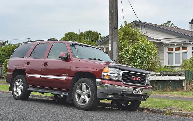
Common on this vehicle:Gauge or instrument faultWarning lightNoiseLeakMisfire or rough idleAir conditioning or heaterCorrosion or rustVibration or shudder
Record by record
65 records state a cause or a remedy. Each record is shown as short labels in the order fault → finding the cause → correction. Press a label to narrow to the records that state it.
Component named as the cause
Work done
How it is said to have ended
- says it came back2
- result not stated1
A ribbon is as wide as the records that state both of its ends (only the commonest are drawn). A record that names several symptoms or components runs through each. Orange is records that say the fault came back or was not fixed. Results come from owners’ reports only; one that does not say is “result not stated”. None of this is a likelihood of a cause or a rate at which work succeeds.
Read the records one by one (18)
Known issuesCastech cylinder head porosity crack (gradual coolant loss)2
Owner complaint2004 GMC YUKON ・ 2013-09-03
Slug buildup, oil pressure loss, and coolant loss
1Fault
2Finding the cause
3Correction
Read the sentences of the record
- Fault
- MY CAR BEGAN TO HAVE A BUILD UP OF SLUGS AND BEGAN LOOSING OIL PRESSURE AND COOLANT AND NEEDED OIL ADDED AND COOLANT FREQUENTLY.
- Cause
- I WAS ADVISED TO CHANGE THE OIL FREQUENTLY TO CLEAN THE SLUG OUT BUT IT CONTINUED TO BUILD UP AND THE MYSTERY OF LOOSING COOLANT OIL PRESSURE HAS BOTTOMED OUT TWO MORE TIMES AND I FOUND A ARTICLE ON THE INTERNET THAT A NUMBER OF GMC VEHICLES INCLUDING MINE WERE BUILT WITH DEFECTIVE CYLINDER HEADS DUE TO CRACKS OVER TIME WHICH ALLOWS COOLANT TO LEAK INTO ENGINE AND MIX WITH THE OIL WHICH BUILDS UP SLUG.
- Remedy
- THE SLUGS WERE CLEANED AND A NEW OIL PUMP WAS PLACED BECAUSE OF THE BUILD UP OF SLUGS.
Manufacturer communication2001–2006 GMC YUKON DENALI ・ 2024-03-19
Internal Coolant Leak from Cylinder Head Location
1Fault
- Some vehicles may experience a gradual coolant loss over time.
2Finding the cause
Possible causes
- A very low percentage of cylinder heads manufactured with an embossed Castech logo may develop a porosity crack in a very specific area.
Steps to confirm (in the document’s order)
- Check whether the head is a Castech casting by looking for the casting logo on top of the intake port, under the rocker arm support rail and in the spring deck cavity portion of the cylinder head.
- If the head is a Castech casting, inspect the area around the five oil drain holes for witness marks indicating coolant seepage over time.
- The crack can be in any of the five cylinder head oil drains and shows as a clean or shiny area on an otherwise stained surface.
- Pressurizing the cooling system at this time may reveal coolant, air, or a combination weeping in the described area.
3Correction
Repair
- If inspection reveals evidence of coolant witness marks, replace the entire cylinder head assembly.
Caution
- If the cylinder heads are not a Castech casting, follow normal diagnostic procedures in SI to determine the cause of the coolant loss.
- If no evidence of coolant loss is found on inspection of Castech casting cylinder heads, follow normal diagnostic procedures in SI to determine the cause of the coolant loss.
Read the sentences of the record
From the manufacturer’s document
- Applies to:Applies to 2001-2006 GMC Envoy, Jimmy, Sierra and Yukon models, among other listed GM models, with the 4.8L, 5.3L or 5.7L VORTEC GEN III, GEN IV V8 engine.
- Condition:Some vehicles may experience a gradual coolant loss over time.
- Cause:A very low percentage of cylinder heads manufactured with an embossed Castech logo may develop a porosity crack in a very specific area.
- Confirm:Check whether the head is a Castech casting by looking for the casting logo on top of the intake port, under the rocker arm support rail and in the spring deck cavity portion of the cylinder head.
- Confirm:If the head is a Castech casting, inspect the area around the five oil drain holes for witness marks indicating coolant seepage over time.
- Confirm:The crack can be in any of the five cylinder head oil drains and shows as a clean or shiny area on an otherwise stained surface.
- Confirm:Pressurizing the cooling system at this time may reveal coolant, air, or a combination weeping in the described area.
- Repair:If inspection reveals evidence of coolant witness marks, replace the entire cylinder head assembly.
- Caution:If the cylinder heads are not a Castech casting, follow normal diagnostic procedures in SI to determine the cause of the coolant loss.
- Caution:If no evidence of coolant loss is found on inspection of Castech casting cylinder heads, follow normal diagnostic procedures in SI to determine the cause of the coolant loss.
Open the manufacturer’s document (PDF) ↗ The points above were read from this document.
- Remedy
- This bulletin advises the technician of possible location of an internal coolant leak from a specific cylinder head and location.
Known issues4L60-E slip or no forward engagement right after input housing replacement (service part 17803687)1
Manufacturer communication2000–2006 GMC YUKON DENALI ・ 2017-08-15
Input Housing Inspection for Forward Range Slip
1Fault
- A few transmissions may slip or have no engagement in any forward gear immediately after the Input Housing (621) is replaced.
2Finding the cause
Possible causes
- The Input Housing (621) from GM Service Parts may have an incorrectly drilled input shaft.
Steps to confirm (in the document’s order)
- With the Input Housing (621) completely assembled, apply regulated compressed air to the 3-4 clutch feed hole and the forward clutch feed hole one at a time.
- Air should not leak out of the 3-4 clutch feed hole when air is applied to the forward clutch feed hole, and not out of the forward clutch feed hole when air is applied to the 3-4 clutch feed hole.
3Correction
Repair
- If air leaks between the two feed holes, replace the Input Housing (621) with one from GM Service Parts, ordering new housing part number 19125752.
Part numbers printed in the document
19125752Housing Assembly,3, 4 Clutch (W/ Input Shaft)Look up at RockAuto (aftermarket candidates) ↗Search the web ↗
Replaced by: 19418733as stated by GMPartsGiant (checked 2026-10-06) ↗Look up at RockAuto (aftermarket candidates) ↗Search the web ↗
The numbers are as the document prints them. The name and the replacing number are what the pages of GMPartsGiant, a reseller of genuine parts and not GM, state. Aftermarket equivalents are not checked here (the links only search by number). Confirm the fit for the vehicle (VIN) before ordering.
Parts
- Part number 19125752, Input Housing And Turbine Shaft Assembly, quantity 1.
Part numbers printed in the document
19125752Housing Assembly,3, 4 Clutch (W/ Input Shaft)Look up at RockAuto (aftermarket candidates) ↗Search the web ↗
Replaced by: 19418733as stated by GMPartsGiant (checked 2026-10-06) ↗Look up at RockAuto (aftermarket candidates) ↗Search the web ↗
The numbers are as the document prints them. The name and the replacing number are what the pages of GMPartsGiant, a reseller of genuine parts and not GM, state. Aftermarket equivalents are not checked here (the links only search by number). Confirm the fit for the vehicle (VIN) before ordering.
Caution
- This information only applies to Input Housing (621) with service part number 17803687; it does not apply to GM service transmission assemblies or original equipment transmission assemblies.
- When testing a fully assembled housing, a small amount of air leaking between the input shaft and the housing does not indicate a defective part.
- Do not replace an Input Housing (621) assembly solely because of a small air leak between the shaft and housing.
Read the sentences of the record
From the manufacturer’s document
- Applies to:The model list includes the 1999-2006 GMC Savana, Sierra, Yukon and Yukon XL.
- Applies to:It applies to vehicles equipped with the 4L60E, 4L65E or 4L70E automatic transmission (RPO M30, M32 or M70) and service input housing part number 17803687.
- Caution:This information only applies to Input Housing (621) with service part number 17803687; it does not apply to GM service transmission assemblies or original equipment transmission assemblies.
- Condition:A few transmissions may slip or have no engagement in any forward gear immediately after the Input Housing (621) is replaced.
- Cause:The Input Housing (621) from GM Service Parts may have an incorrectly drilled input shaft.
- Confirm:With the Input Housing (621) completely assembled, apply regulated compressed air to the 3-4 clutch feed hole and the forward clutch feed hole one at a time.
- Confirm:Air should not leak out of the 3-4 clutch feed hole when air is applied to the forward clutch feed hole, and not out of the forward clutch feed hole when air is applied to the 3-4 clutch feed hole.
- Repair:If air leaks between the two feed holes, replace the Input Housing (621) with one from GM Service Parts, ordering new housing part number 19125752.
- Caution:When testing a fully assembled housing, a small amount of air leaking between the input shaft and the housing does not indicate a defective part.
- Caution:Do not replace an Input Housing (621) assembly solely because of a small air leak between the shaft and housing.
- Parts:Part number 19125752, Input Housing And Turbine Shaft Assembly, quantity 1.
Open the manufacturer’s document (PDF) ↗ The points above were read from this document.
- Remedy
- This Preliminary Information communication provides information to the technician about vehicles that have slip in forward ranges immediately after replacing the input housing. Technician will inspect the 3-4 clutches and the forward clutch oil feed passages for leakage between circuits. Technician should apply regulated compressed air to the 3-4 clutch feed hole and the forward clutch feed hole one at a time with the input housing. Technician will need to replace the input housing if there is an air leak 3-4 clutches.
Known issuesBrake pipe (brake line) corrosion and rupture1
Owner complaint2004 GMC YUKON ・ 2018-05-29
Brake pedal depression to floor and brake line failures due to rust at 260K miles
1Fault
2Finding the cause
3Correction
Not stated
What the documents say to do
Brake pipe (brake line) corrosion and ruptureConfirm
- In the joint inspections, scaling or flaking corrosion was taken as indicating the onset of metal loss and given the second lowest ranking (2); a leaking or previously repaired pipe was the lowest (1).
Repair
- GM recommends replacing the entire set of pipes whenever any pipe leaks or is corroded enough to need replacement.
- On June 28, 2013 GM released 66 new part numbers for servicing brake pipes in 1999-2007 GMT800 pickups and utility vehicles.
Caution
- Analysis of repair records indicates that consumers often elect to repair only the failed circuit.
Read the sentences of the record
- Fault
- WHILE TRAVELING AT HIGHWAY SPEED AND ROUNDING A BLIND CURVE THE TRAFFIC AHEAD HAD STOPPED DUE TO A CRASH. (1 more)
- Inspection
- IT WAS RAINING AND AS I LOOKED UNDER MY TRUCK TO LOOK FOR WHY MY BRAKES WERE INEFFECTIVE BUT COULDN'T SEE ANYTHING AT THAT TIME. (1 more)
- Consequence
- I WASN'T STOPPING NEAR FAST ENOUGH AND HAD TO VEER TO THE LEFT INTO THE MEDIAN TO AVOID MAKING CONTACT WITH ANYONE ELSE.
Known issuesAftermarket part (not the vehicle as built): Fram G3727 replacement fuel filter connector - recall 06E-0431
Recall2004 GMC YUKON ・ —
Fram Replacement Fuel Filters (P/N G3727) Recall
1Fault
- The connector on the fuel filter was not manufactured to specification, so the O-ring may not seat correctly on the fuel line; this may cause an inadequate seal, potentially leading to a fuel leak (wetting or dripping) and possible vehicle fire.
2Finding the cause
Steps to confirm (in the document’s order)
- The part number (G3727), country of origin (Mexico) and the date code (e.g., X60031) are located on the side of the fuel filter.
3Correction
Repair
- Honeywell will replace the subject fuel filters at no charge to the customer.
Read the sentences of the record
From the manufacturer’s document
- Applies to:This is an equipment recall of fuel filters manufactured by Interfil in Mexico and sold by Honeywell under the FRAM brand name, part number G3727, intended for aftermarket installation on the vehicle applications in the attached table.
- Applies to:Only filters with date codes X52911 through X60801 sequentially or X600141, and with a Mexico country of origin marking on the filter housing, are subject to the recall.
- Applies to:The application table lists YUKON 1992 - 2005, YUKON DENALI 2005, YUKON DENALI XL 2005, YUKON XL 1500 2000 - 2005 and YUKON XL 2500 2000 - 2005.
- Condition:The connector on the fuel filter was not manufactured to specification, so the O-ring may not seat correctly on the fuel line; this may cause an inadequate seal, potentially leading to a fuel leak (wetting or dripping) and possible vehicle fire.
- Confirm:The part number (G3727), country of origin (Mexico) and the date code (e.g., X60031) are located on the side of the fuel filter.
- Repair:Honeywell will replace the subject fuel filters at no charge to the customer.
- Cause
- CERTAIN REPLACEMENT FUEL FILTERS, FRAM BRAND NAME P/N G3727, WITH DATE CODES X52911 THROUGH X60801 SEQUENTIALLY OR X600141 AND A MEXICO COUNTRY OR ORIGIN MARKING ON THE FUEL FILTER HOUSING MANUFACTURED FROM OCTOBER 18, 2005, THROUGH MARCH 21, 2006, SOLD FOR USE ON THE VEHICLES LISTED ABOVE AND ON CERTAIN SCHOOL BUSES. (TO SEE THE SCHOOL BUS ENGINE SIZES, CLICK ON "DOCUMENT SEARCH" AND THEN "BUS APPLICATIONS"). THE CONNECTOR ON THE FUEL FILTER WAS NOT MANUFACTURED TO HONEYWELL'S SPECIFICATION. AS A RESULT, THE O-RING MAY NOT SEAT CORRECTLY ON THE FUEL LINE.
- Remedy
- HONEYWELL WILL NOTIFY OWNERS AND REPLACE THE FUEL FILTERS FREE OF CHARGE. THE RECALL BEGAN ON OCTOBER 18, 2006. OWNERS MAY CONTACT FRAM CUSTOMER SERVICE AT 1-800-890-2075 (OPTION 1).
- Consequence
- THIS CONDITION MAY CAUSE AN INADEQUATE SEAL AT THE CONNECTION, POTENTIALLY LEADING TO A FUEL LEAK. IN THE PRESENCE OF AN IGNITION SOURCE, A FIRE COULD OCCUR.
Known issuesGrease seen at front hub bearing seals (normal purge, do not replace)1
Manufacturer communication2004–2006 GMC YUKON DENALI ・ 2017-08-15
Front hub bearing grease leakage preliminary information
1Fault
- Grease may move radially outward from the bearing seal area onto adjoining components.
2Finding the cause
Possible causes
- The factory grease fill of the front bearing/hub assembly is more than the bearing needs for lubrication over the life of the vehicle.
- Part of the grease purges through the self-venting bearing seals during the initial drive period (a few thousand miles/kilometers) and helps form an extra barrier against contamination.
Steps to confirm (in the document’s order)
- Replace the bearing if its endplay is greater than 0.005" or 0.13mm.
- Replace the bearing if the seals show visible damage.
- Replace the bearing if it rotates roughly.
- Replace the bearing if it makes abnormal noise.
3Correction
Repair
- If desired, grease that has migrated away from the immediate seal area can be wiped off.
Caution
- Do not replace the bearing for grease purge, and do not clean the purged grease on or right next to the seals, because it gives additional protection.
Read the sentences of the record
From the manufacturer’s document
- Applies to:Applies to 2004-2013 GMC Sierra, Sierra Classic, Yukon and Yukon Denali models (note: the Yukon years run later than the years this service covers).
- Condition:Grease may move radially outward from the bearing seal area onto adjoining components.
- Cause:The factory grease fill of the front bearing/hub assembly is more than the bearing needs for lubrication over the life of the vehicle.
- Cause:Part of the grease purges through the self-venting bearing seals during the initial drive period (a few thousand miles/kilometers) and helps form an extra barrier against contamination.
- Caution:Do not replace the bearing for grease purge, and do not clean the purged grease on or right next to the seals, because it gives additional protection.
- Repair:If desired, grease that has migrated away from the immediate seal area can be wiped off.
- Confirm:Replace the bearing if its endplay is greater than 0.005" or 0.13mm.
- Confirm:Replace the bearing if the seals show visible damage.
- Confirm:Replace the bearing if it rotates roughly.
- Confirm:Replace the bearing if it makes abnormal noise.
Open the manufacturer’s document (PDF) ↗ The points above were read from this document.
- Remedy
- This Preliminary Information communication provides information to the technician about vehicles that have grease leaking from front hub bearings. Technician should not replace the bearing for grease purge. Technician should be advised to not clean the purged grease from the area immediately on or adjacent to the seals because this grease provides additional protection. Technician should only replace the bearing if the seals show visible damage, bearing endplay is greater than 0.005" or 0.13mm, bearing exhibits rough rotation, or bearing exhibits abnormal noise.
Known issuesSingle-cylinder misfire (P0300-P0308) and/or chirp, squeak or tick at camshaft speed: worn cam lobe / lifter, valve or valve spring1
Manufacturer communication2002–2006 GMC YUKON DENALI ・ 2018-11-13(4 earlier editions of this document folded here)
Service Engine Soon Lamp, Misfire, Engine Noise Diagnostic Information
1Fault
- Customers may complain of an SES light, engine misfire, and/or engine noise.
- If the SES light is on, there will be a P0300-P0308 DTC with misfires counting on a single cylinder, which may or may not be felt.
- A verified noise is not eliminated by canceling fuel injectors and occurs at camshaft speed (half of crankshaft speed).
2Finding the cause
- Valve Spring: broken
- Active Fuel Management Lifter: failed
- Valve: defective
- Camshaft Lobe: worn
- Lifter Roller: worn
Possible causes
- If SI diagnosis does not isolate the cause, it may be a worn camshaft lobe and/or lifter roller, a sticking valve, valve leakage, a broken valve spring, or a collapsed AFM (Active Fuel Management) lifter.
Steps to confirm (in the document’s order)
- During the noise, press with a wooden hammer handle on the rocker arms at the valve side, push rod side, and side of the rocker to find which one is making noise.
- If pressure on the valve side of the rocker changes the noise, it is most likely a lifter and/or cam lobe concern on that cylinder.
- Measure the cam lobe lift at the push rod side of the rocker arm.
- A good indicator of a sticking valve is engine misfires that continue to count on an aggressive deceleration with engine braking.
- Release the air pressure from the cylinder and work the valve up and down in the guide while turning it 360 degrees; if any binding is felt, a stem to guide clearance concern exists.
3Correction
Repair
- If a worn camshaft lobe or lifter roller is found, follow SI procedures to replace the camshaft and all lifters.
- Also replace the plastic lifter guide for the lifter that had the damaged cam lobe and/or lifter roller.
- Refer to the latest version of PIP4753 for decarboning instructions.
- If a broken valve spring is found, replace the broken valve spring as necessary.
Caution
- If an AFM lifter concern is suspected, refer to the latest version of PIP4568 for additional information.
Read the sentences of the record
From the manufacturer’s document
- Applies to:Applies to GMC Yukon models, 2002 - 2018, with a V8 engine.
- Condition:Customers may complain of an SES light, engine misfire, and/or engine noise.
- Condition:If the SES light is on, there will be a P0300-P0308 DTC with misfires counting on a single cylinder, which may or may not be felt.
- Condition:A verified noise is not eliminated by canceling fuel injectors and occurs at camshaft speed (half of crankshaft speed).
- Cause:If SI diagnosis does not isolate the cause, it may be a worn camshaft lobe and/or lifter roller, a sticking valve, valve leakage, a broken valve spring, or a collapsed AFM (Active Fuel Management) lifter.
- Confirm:During the noise, press with a wooden hammer handle on the rocker arms at the valve side, push rod side, and side of the rocker to find which one is making noise.
- Confirm:If pressure on the valve side of the rocker changes the noise, it is most likely a lifter and/or cam lobe concern on that cylinder.
- Confirm:Measure the cam lobe lift at the push rod side of the rocker arm.
- Repair:If a worn camshaft lobe or lifter roller is found, follow SI procedures to replace the camshaft and all lifters.
- Repair:Also replace the plastic lifter guide for the lifter that had the damaged cam lobe and/or lifter roller.
- Confirm:A good indicator of a sticking valve is engine misfires that continue to count on an aggressive deceleration with engine braking.
- Confirm:Release the air pressure from the cylinder and work the valve up and down in the guide while turning it 360 degrees; if any binding is felt, a stem to guide clearance concern exists.
- Repair:Refer to the latest version of PIP4753 for decarboning instructions.
- Confirm:Typically, the Cylinder Leakage Test outlined in SI should isolate valve leakage.
- Repair:If a broken valve spring is found, replace the broken valve spring as necessary.
- Caution:If an AFM lifter concern is suspected, refer to the latest version of PIP4568 for additional information.
Open the manufacturer’s document (PDF) ↗ The points above were read from this document.
- Remedy
- This Preliminary Information communication provides information to the technician about vehicles that have a Service Engine Soon Malfunction Indicator Lamp on, engine misfire, and/or engine noise. Technician may find Diagnostic Trouble Codes P0300-P0308. If published Service Information diagnostics does not isolate the cause of this concern technician should check for a worn camshaft lobe and/or lifter roller, a sticking valve, valve leakage, a broken valve spring, and a collapsed active fuel management lifter.
Known issuesOil leak after cold start from frozen PCV system (rear main seal)1
Manufacturer communication2002–2006 GMC YUKON DENALI ・ 2018-02-21
Oil Leak at Cold Start in Extreme Low Ambient Temperatures
1Fault
- An oil leak may appear shortly after a cold start in extremely low ambient temperatures (approximately below 10*F) or with excessive short trip drive cycles.
2Finding the cause
Possible causes
- An oil leak from the rear main seal is the result of a frozen PCV system and excessive crankcase pressure.
3Correction
Repair
- Clean the area of the oil leak, clean and dry the PCV hoses, and replace the oil fill cap with part number 12589430 (vented oil fill cap) to prevent a reoccurrence.
- For warranty repairs, labor operation 4065230 is Oil Filler Cap Replacement.
Part numbers printed in the document
12589430Oil Filler CapLook up at RockAuto (aftermarket candidates) ↗Search the web ↗
No successor stated(replaces 21007373 / 24100010 / 24100296 / 12573342)as stated by GMPartsGiant (checked 2026-10-06) ↗
The numbers are as the document prints them. The name and the replacing number are what the pages of GMPartsGiant, a reseller of genuine parts and not GM, state. Aftermarket equivalents are not checked here (the links only search by number). Confirm the fit for the vehicle (VIN) before ordering.
Parts
- Oil fill cap part number 12589430 (vented oil fill cap).
Part numbers printed in the document
12589430Oil Filler CapLook up at RockAuto (aftermarket candidates) ↗Search the web ↗
No successor stated(replaces 21007373 / 24100010 / 24100296 / 12573342)as stated by GMPartsGiant (checked 2026-10-06) ↗
The numbers are as the document prints them. The name and the replacing number are what the pages of GMPartsGiant, a reseller of genuine parts and not GM, state. Aftermarket equivalents are not checked here (the links only search by number). Confirm the fit for the vehicle (VIN) before ordering.
Read the sentences of the record
From the manufacturer’s document
- Applies to:Applies to GMC Yukon models, 2002 - 2014, with a V8 engine.
- Condition:An oil leak may appear shortly after a cold start in extremely low ambient temperatures (approximately below 10*F) or with excessive short trip drive cycles.
- Cause:An oil leak from the rear main seal is the result of a frozen PCV system and excessive crankcase pressure.
- Repair:Clean the area of the oil leak, clean and dry the PCV hoses, and replace the oil fill cap with part number 12589430 (vented oil fill cap) to prevent a reoccurrence.
- Parts:Oil fill cap part number 12589430 (vented oil fill cap).
- Repair:For warranty repairs, labor operation 4065230 is Oil Filler Cap Replacement.
Open the manufacturer’s document (PDF) ↗ The points above were read from this document.
- Remedy
- This Preliminary Information communication provides information to the technician about vehicles that have an oil leak shortly after a cold start when extremely low ambient temperatures are present. Technician will need to clean the area of the oil leak, clean and dry the PCV hoses, and replace the oil fill cap with part number 12589430.
ENGINE AND ENGINE COOLING5
Manufacturer communication2000–2006 GMC YUKON DENALI ・ 2023-04-12(4 earlier editions of this document folded here)
ACDelco Spin-On Oil Filter Torque Specification Notification
1Fault
- An oil leak from underneath the front of the vehicle after an earlier oil service; the leak can take several thousand miles to appear.
2Finding the cause
Possible causes
- The oil may be leaking from between the oil filter gasket and the mounting surface.
Steps to confirm (in the document’s order)
- The filter may be very easy to remove, sometimes by hand.
3Correction
Repair
- Lubricate the new oil filter gasket with clean engine oil.
- Install the oil filter 1 full turn after the gasket contacts the sealing surface on the filter mounting flange.
Read the sentences of the record
From the manufacturer’s document
- Applies to:Applies to all passenger cars and trucks, model years 2000 to 2024.
- Condition:An oil leak from underneath the front of the vehicle after an earlier oil service; the leak can take several thousand miles to appear.
- Cause:The oil may be leaking from between the oil filter gasket and the mounting surface.
- Confirm:The filter may be very easy to remove, sometimes by hand.
- Repair:Lubricate the new oil filter gasket with clean engine oil.
- Repair:Install the oil filter 1 full turn after the gasket contacts the sealing surface on the filter mounting flange.
Open the manufacturer’s document (PDF) ↗ The points above were read from this document.
- Remedy
- This service bulletin provides service information on new torque specification and installation procedure for ACDelco Spin-On Oil Filters.
Manufacturer communication2000–2006 GMC YUKON DENALI ・ 2023-01-06(2 earlier editions of this document folded here)
EVAP Leak Diagnostic Service Bulletin (DTCs P0442/P0455)
1Fault
- The MIL is illuminated, and DTC P0442 (EVAP small leak detected) and/or P0455 (EVAP large leak detected) may be set in the ECM.
2Finding the cause
Possible causes
- P0455 sets because of a large leak or a purge blockage: an unseated tube connection, a damaged tube, a canister vent valve stuck open, or a purge valve stuck closed.
- P0442 sets because of a small leak, which can come from a purge valve stuck open or a canister vent valve stuck open.
Steps to confirm (in the document’s order)
- Inspect every purge connection for proper installation, and look along the lines for damage or wear; if damage is seen, confirm it with the smoke test.
- Some leaks show only under pressure and some only under vacuum, so check both ways; cycling the purge and vent solenoids with GDS2 while inspecting may show a sticking valve.
- Critical connections to check include: purge tube to purge valve (at the intake manifold), purge tube to chassis EVAP line (rear of the engine, near the transmission), chassis EVAP line to canister, and fuel tank load line to canister.
- Also check the vent valve line at the vent valve, the fuel tank load line jumper connection near the fuel tank, and that the fuel tank cap is closed properly.
- If all connections are good, check the vent valve for a stuck-open position; if the vent valve works correctly, go on to the purge valve.
3Correction
Parts
- No parts are required for this repair.
Caution
- For diagnostic instructions, DTC information and required tools, always follow the service information document for the vehicle and DTC being worked on.
Read the sentences of the record
From the manufacturer’s document
- Applies to:This bulletin only applies to vehicles with gasoline engines.
- Condition:The MIL is illuminated, and DTC P0442 (EVAP small leak detected) and/or P0455 (EVAP large leak detected) may be set in the ECM.
- Cause:P0455 sets because of a large leak or a purge blockage: an unseated tube connection, a damaged tube, a canister vent valve stuck open, or a purge valve stuck closed.
- Cause:P0442 sets because of a small leak, which can come from a purge valve stuck open or a canister vent valve stuck open.
- Confirm:Inspect every purge connection for proper installation, and look along the lines for damage or wear; if damage is seen, confirm it with the smoke test.
- Confirm:Some leaks show only under pressure and some only under vacuum, so check both ways; cycling the purge and vent solenoids with GDS2 while inspecting may show a sticking valve.
- Confirm:Critical connections to check include: purge tube to purge valve (at the intake manifold), purge tube to chassis EVAP line (rear of the engine, near the transmission), chassis EVAP line to canister, and fuel tank load line to canister.
- Confirm:Also check the vent valve line at the vent valve, the fuel tank load line jumper connection near the fuel tank, and that the fuel tank cap is closed properly.
- Confirm:If all connections are good, check the vent valve for a stuck-open position; if the vent valve works correctly, go on to the purge valve.
- Confirm:Work in this order: EVAP lines properly installed and fully seated; damage on the EVAP lines; vent valve malfunction; purge valve malfunction.
- Parts:No parts are required for this repair.
- Caution:For diagnostic instructions, DTC information and required tools, always follow the service information document for the vehicle and DTC being worked on.
Open the manufacturer’s document (PDF) ↗ The points above were read from this document.
- Remedy
- This service bulletin provides diagnostic tips/steps on testing for possible EVAP leaks in the system to correct a customer concern of an MIL Illuminated with DTCs P0442 and/or P0455 Set.
Manufacturer communication2000–2006 GMC YUKON DENALI ・ 2022-09-07
MIL Illuminated with Fuel Trim and Oxygen Sensor Codes
1Fault
- Customers may comment that the MIL is illuminated.
- Initial diagnosis may show fuel trim and O2 sensor related codes including P0101, P0137, P0138, P0140, P0141, P0157, P0158, P0160 and P0161.
- The listed codes also include P0171, P0174, P0420, P0430, P1174 and P1175.
2Finding the cause
Possible causes
- These methods find small leaks around the O2 sensor embossments and slight cracks in an intake plenum or gasket.
Steps to confirm (in the document’s order)
- If normal SI diagnostics do not lead to a resolution and an intake vacuum leak or exhaust leak is suspected, use the GE-52250 Variable Pressure Leak Detector (preferred), the J-41416 ultrasonic leak tester, or possibly soapy water with low pressure air into the tailpipe to find the leak.
- For an intake leak, introduce the smoke into the brake booster hose or the oil dipstick tube; soapy water can be sprayed near the gasket, seams and all vacuum nipples.
- For an exhaust leak, put the hose with smoke or air into the tailpipe sealed with shop towels, then spray soapy water around seals, seams and bosses.
3Correction
Parts
- No parts are required for this repair.
Caution
- All of these tests are much more effective if the throttle body is covered or sealed.
Read the sentences of the record
From the manufacturer’s document
- Applies to:Applies to Buick, Cadillac, Chevrolet and GMC passenger cars and trucks, model years 2000 to 2022, gasoline engines only.
- Condition:Customers may comment that the MIL is illuminated.
- Condition:Initial diagnosis may show fuel trim and O2 sensor related codes including P0101, P0137, P0138, P0140, P0141, P0157, P0158, P0160 and P0161.
- Condition:The listed codes also include P0171, P0174, P0420, P0430, P1174 and P1175.
- Confirm:If normal SI diagnostics do not lead to a resolution and an intake vacuum leak or exhaust leak is suspected, use the GE-52250 Variable Pressure Leak Detector (preferred), the J-41416 ultrasonic leak tester, or possibly soapy water with low pressure air into the tailpipe to find the leak.
- Caution:All of these tests are much more effective if the throttle body is covered or sealed.
- Confirm:For an intake leak, introduce the smoke into the brake booster hose or the oil dipstick tube; soapy water can be sprayed near the gasket, seams and all vacuum nipples.
- Confirm:For an exhaust leak, put the hose with smoke or air into the tailpipe sealed with shop towels, then spray soapy water around seals, seams and bosses.
- Cause:These methods find small leaks around the O2 sensor embossments and slight cracks in an intake plenum or gasket.
- Parts:No parts are required for this repair.
Open the manufacturer’s document (PDF) ↗ The points above were read from this document.
- Remedy
- This bulletin provides information on tools available to find an intake vacuum leak or exhaust leak to correct a condition of MIL Illuminated with Multiple Fuel Trim and/or Oxygen Sensor Codes Set.
Manufacturer communication2000–2006 GMC YUKON DENALI ・ 2019-03-18
Diagnostic Tip: Using Smoke Machine and Ultrasonic Detector for Air Leaks
1Fault
- The SES light is on, and initial diagnosis may show fuel trim and/or O2 sensor related codes such as P0171, P0174, P0420 and P0430.
2Finding the cause
Steps to confirm (in the document’s order)
- If normal SI diagnostics do not resolve it and an intake vacuum leak or exhaust leak is suspected, the J41413-200 Evaporative System Tester smoke machine, the J-41416 ultrasonic leak tester, or soapy water with low pressure air into the tailpipe may help find the leak.
- For an intake leak, the smoke can be introduced into the brake booster hose or the oil dipstick tube.
- Soapy water can be sprayed near the gasket and seams and on all vacuum nipples.
- For an exhaust leak, a hose into the tailpipe carrying smoke or air, sealed with shop towels, is effective.
- Then spray soapy water around the seals, seams and bosses.
3Correction
Caution
- All of these tests are much more effective if the throttle body is covered/sealed.
Read the sentences of the record
From the manufacturer’s document
- Applies to:Applies to all 2000 - 2019 models with gasoline engines.
- Condition:The SES light is on, and initial diagnosis may show fuel trim and/or O2 sensor related codes such as P0171, P0174, P0420 and P0430.
- Confirm:If normal SI diagnostics do not resolve it and an intake vacuum leak or exhaust leak is suspected, the J41413-200 Evaporative System Tester smoke machine, the J-41416 ultrasonic leak tester, or soapy water with low pressure air into the tailpipe may help find the leak.
- Caution:All of these tests are much more effective if the throttle body is covered/sealed.
- Confirm:For an intake leak, the smoke can be introduced into the brake booster hose or the oil dipstick tube.
- Confirm:Soapy water can be sprayed near the gasket and seams and on all vacuum nipples.
- Confirm:For an exhaust leak, a hose into the tailpipe carrying smoke or air, sealed with shop towels, is effective.
- Confirm:Then spray soapy water around the seals, seams and bosses.
- Confirm:These methods are very good for finding small leaks around the O2 sensor bosses and slight cracks in an intake plenum or gasket.
Open the manufacturer’s document (PDF) ↗ The points above were read from this document.
- Remedy
- This preliminary information document communicates a tip on the way to diagnose possible induction or exhaust air leaks using the evaporative emission cart smoke machine and ultrasonic leak detector tools.
Manufacturer communication2000–2006 GMC YUKON DENALI ・ 2017-08-15
Engine Check Lamp P0442 Evaporative Emissions System Notification
1Fault
- The service engine soon lamp (MIL) is on for DTC P0442, but a leak cannot be verified with the system test in the service information.
2Finding the cause
Steps to confirm (in the document’s order)
- With the scan tool, command the EVAP system CLOSED, start the engine and watch the tank pressure sensor value for about two minutes.
- If the tank pressure value changes (shows vacuum), remove the purge solenoid and pressurize its fuel tank side with the GE 41413-A / J 41413-A tester.
- If the tank pressure value does not change, install the CH-48096 adaptor between the purge line from the canister and the purge solenoid; use no other adaptor or pressurization method.
- With the EVAP system CLOSED, pressurize through the adaptor and let the system stabilize, watching the gauge for at least 5 minutes, then add smoke.
- Look for smoke or UV trace fluid at the purge solenoid, the engine side, the fuel cap or capless fill door, and the canister vent solenoid filter or fresh-air line.
3Correction
Repair
- If smoke passes through the purge solenoid, replace the purge solenoid.
Caution
- After verifying P0442, do not disturb any fuel system component before testing.
- Test pressure must not exceed 13 in H2O (0.5 PSI (= 3.45 kPa)); more can make components perform inaccurately and lead to misdiagnosis.
- A large temperature difference between vehicle, shop and tester seriously affects accuracy; let the vehicle adjust to shop temperature first.
Read the sentences of the record
From the manufacturer’s document
- Applies to:Applies to 2016 and prior passenger cars and trucks.
- Condition:The service engine soon lamp (MIL) is on for DTC P0442, but a leak cannot be verified with the system test in the service information.
- Caution:After verifying P0442, do not disturb any fuel system component before testing.
- Confirm:With the scan tool, command the EVAP system CLOSED, start the engine and watch the tank pressure sensor value for about two minutes.
- Confirm:If the tank pressure value changes (shows vacuum), remove the purge solenoid and pressurize its fuel tank side with the GE 41413-A / J 41413-A tester.
- Repair:If smoke passes through the purge solenoid, replace the purge solenoid.
- Confirm:If the tank pressure value does not change, install the CH-48096 adaptor between the purge line from the canister and the purge solenoid; use no other adaptor or pressurization method.
- Confirm:With the EVAP system CLOSED, pressurize through the adaptor and let the system stabilize, watching the gauge for at least 5 minutes, then add smoke.
- Confirm:Look for smoke or UV trace fluid at the purge solenoid, the engine side, the fuel cap or capless fill door, and the canister vent solenoid filter or fresh-air line.
- Confirm:If smoke testing finds nothing, the leak may exist only under vacuum: use the scan tool Purge/Seal function to pull a vacuum and watch the FTP sensor parameter for vacuum decay.
- Caution:Test pressure must not exceed 13 in H2O (0.5 PSI (= 3.45 kPa)); more can make components perform inaccurately and lead to misdiagnosis.
- Caution:A large temperature difference between vehicle, shop and tester seriously affects accuracy; let the vehicle adjust to shop temperature first.
Open the manufacturer’s document (PDF) ↗ The points above were read from this document.
- Remedy
- This Preliminary Information communication provides information to the technician about vehicles that have a Service Engine Soon Malfunction Indicator Lamp. Technician may find Diagnostic Trouble Code P0442. Technician will need to review Techlink article from May 2013 titled "Using the Evaporative Emissions System Tester" Technician will need to follow these steps to help diagnose the issue. First after the P0442 has been verified do not disturb any of the fuel system components. The technician now can use the scan tool to close the Evaporative Emissions System. If possible change the tank pressure sensor units from inch_H2O to milimeter_Hg for better resolution. Now the vehicle can be stared to monitor the tank pressure sensor output value for approximately two minutes. If the tank pressure sensor value does change, pressurize the fuel tank side of the purge solenoid with the GE 41413-A / J 41413-A and the necessary adaptors. Now add smoke and allow pressure to stabilize for 2 minutes. If smoke is allowed to pass through the purge solenoid, replace the purge solenoid. If the tank pressure sensor value does not change, then install CH-48096 adaptor between the purge line from the canister and the purge solenoid. With the Evaporative Emissions System closed, pressurize the system through the CH-48096 adaptor and allow the system to completely stabilize, by observing the Press / Vac Gauge for a minimum of 5 minutes. Now add smoke to the system with GE 41413-A / J 41413-A after system stabilization. Now inspect the purge solenoid, engine side, fuel cap, canister vent solenoid filter and any line quick connects. When the leak is unable to be located, test under a vacuum condition. his type of leak may be detected by using the scan tool Purge/Seal function to create a vacuum in the Evaporative Emissions System and then observe the FTP sensor parameter for vacuum decay.
EQUIPMENT2
Manufacturer communication2000–2006 GMC YUKON DENALI ・ 2018-06-11(4 earlier editions of this document folded here)
GM Products for Eliminating Vehicle Odors
1Fault
- GM Vehicle Care Odor Eliminator has been shown to greatly reduce or remove mold and mildew smells resulting from vehicle water leaks, as well as customer created odors such as smoke.
2Finding the cause
Steps to confirm (in the document’s order)
- First confirm that all water leaks have been repaired and determine which areas were water soaked or wet; components with visible mold/mildew staining should be replaced.
3Correction
Repair
- If the interior is removed, treat the floor pan and primed/painted surfaces with a bleach/soap solution, rinse with clean water and dry.
- For hard surfaces, add 8 oz. of GM Vehicle Care Odor Eliminator (1 cup) to dish soap in a spray bottle and top off the bottle with tap water.
- Treat all carpeting and upholstered seats lightly to moderately with the formula at full strength, using a wide fan spray setting.
- For the ventilation system, start the vehicle, turn the fan on high cool (not the A/C setting), and spray the formula (10 trigger pulls) into the outside fresh air intake vent at the cowl.
Parts
- Part number 88861431 (in Canada, 88861436): GM Vehicle Care Odor Eliminator, 32 oz (946 mL) non-aerosol bottle.
Part numbers printed in the document
88861431Odor Eliminator, Spray Acdelco 32OzLook up at RockAuto (aftermarket candidates) ↗Search the web ↗
Discontinued (no successor stated)as stated by GMPartsGiant (checked 2026-10-06) ↗
88861436Look up at RockAuto (aftermarket candidates) ↗Search the web ↗
The numbers are as the document prints them. The name and the replacing number are what the pages of GMPartsGiant, a reseller of genuine parts and not GM, state. Aftermarket equivalents are not checked here (the links only search by number). Confirm the fit for the vehicle (VIN) before ordering.
Caution
- Do not let the product come into contact with vinegar or any acidic substance.
Read the sentences of the record
From the manufacturer’s document
- Applies to:Applies to 2015 and prior GM passenger cars and trucks.
- Condition:GM Vehicle Care Odor Eliminator has been shown to greatly reduce or remove mold and mildew smells resulting from vehicle water leaks, as well as customer created odors such as smoke.
- Caution:Do not let the product come into contact with vinegar or any acidic substance.
- Confirm:First confirm that all water leaks have been repaired and determine which areas were water soaked or wet; components with visible mold/mildew staining should be replaced.
- Repair:If the interior is removed, treat the floor pan and primed/painted surfaces with a bleach/soap solution, rinse with clean water and dry.
- Repair:For hard surfaces, add 8 oz. of GM Vehicle Care Odor Eliminator (1 cup) to dish soap in a spray bottle and top off the bottle with tap water.
- Repair:Treat all carpeting and upholstered seats lightly to moderately with the formula at full strength, using a wide fan spray setting.
- Repair:For the ventilation system, start the vehicle, turn the fan on high cool (not the A/C setting), and spray the formula (10 trigger pulls) into the outside fresh air intake vent at the cowl.
- Parts:Part number 88861431 (in Canada, 88861436): GM Vehicle Care Odor Eliminator, 32 oz (946 mL) non-aerosol bottle.
Open the manufacturer’s document (PDF) ↗ The points above were read from this document.
- Remedy
- This informational bulletin provides information on what products GM has to aid in the eliminating unwanted odors in a vehicle.
Manufacturer communication2003–2006 GMC YUKON DENALI ・ 2018-04-23
Fix It Right for First Time Information
1Fault
- It is a table of field product reminders listing, per model year and vehicle line/condition, what to do, what not to do, and the reference bulletin.
- The only row naming Yukon covers 2007-2013 Yukon XL Denali, Yukon Denali, Yukon XL and Yukon (with other listed trucks): a hydraulic power steering leak at the hose connection to the steering rack.
2Finding the cause
Not stated
3Correction
Repair
- For that leak the table says to verify the leak with dye and replace the Duckbill seal using J-42640 if necessary, and not to replace the steering gear or lines; the reference is 12-02-32-001A.
Read the sentences of the record
From the manufacturer’s document
- Applies to:The bulletin is addressed to 2013 and prior GM passenger cars and trucks.
- Condition:It is a table of field product reminders listing, per model year and vehicle line/condition, what to do, what not to do, and the reference bulletin.
- Condition:The only row naming Yukon covers 2007-2013 Yukon XL Denali, Yukon Denali, Yukon XL and Yukon (with other listed trucks): a hydraulic power steering leak at the hose connection to the steering rack.
- Repair:For that leak the table says to verify the leak with dye and replace the Duckbill seal using J-42640 if necessary, and not to replace the steering gear or lines; the reference is 12-02-32-001A.
Open the manufacturer’s document (PDF) ↗ The points above were read from this document.
- Remedy
- This informational bulletin provides information on fix it right for first time issues.
EXTERIOR LIGHTING1
Manufacturer communication2000–2006 GMC YUKON DENALI ・ 2023-02-28(1 earlier editions of this document folded here)
Exterior Lamp Condensation and Water Leaks Service Bulletin
1Fault
- Exterior lamps such as cornering, turn signal, backup, head or tail lamps may show very small water droplets, a fine mist or white fog (condensation) on the inside of the lens.
2Finding the cause
Possible causes
- Condensation occurs when the air inside the lamp assembly reaches the dew point through atmospheric changes.
- Non-OE lamps are most often presented as holding moisture or with inoperative bulbs from corroded electrical connections; they appear to be installed as part of a collision repair.
Steps to confirm (in the document’s order)
- Normal: the mist is located mainly in the lens corners near the vents and does not cover more than half the lens surface.
- Normal: the moisture clears when the vehicle is parked in a dry environment or driven with the lights on.
- Leak: water has accumulated in the bottom of the lamp assembly.
- Leak: the condition will not clear when the vehicle is parked in a dry environment or driven with the lights on.
3Correction
Repair
- A condition covering more than half the surface of the lamp lens indicates the need to service the lens or lamp assembly.
Caution
- Depending on the lamp and the atmospheric conditions, the time needed to clear the lamp may vary from 2 to 6 hours.
- If the normal conditions are noted, advise the customer that replacing the lamp assembly may not correct the condition.
- Moisture that "comes and goes" is considered a normal condition.
Read the sentences of the record
From the manufacturer’s document
- Applies to:Applies to 2023 and prior GM passenger cars and trucks, including medium duty trucks and excluding LCF medium duty trucks.
- Condition:Exterior lamps such as cornering, turn signal, backup, head or tail lamps may show very small water droplets, a fine mist or white fog (condensation) on the inside of the lens.
- Cause:Condensation occurs when the air inside the lamp assembly reaches the dew point through atmospheric changes.
- Caution:Depending on the lamp and the atmospheric conditions, the time needed to clear the lamp may vary from 2 to 6 hours.
- Confirm:Normal: the mist is located mainly in the lens corners near the vents and does not cover more than half the lens surface.
- Confirm:Normal: the moisture clears when the vehicle is parked in a dry environment or driven with the lights on.
- Caution:If the normal conditions are noted, advise the customer that replacing the lamp assembly may not correct the condition.
- Repair:A condition covering more than half the surface of the lamp lens indicates the need to service the lens or lamp assembly.
- Confirm:Leak: water has accumulated in the bottom of the lamp assembly.
- Confirm:Leak: the condition will not clear when the vehicle is parked in a dry environment or driven with the lights on.
- Caution:Moisture that "comes and goes" is considered a normal condition.
- Cause:Non-OE lamps are most often presented as holding moisture or with inoperative bulbs from corroded electrical connections; they appear to be installed as part of a collision repair.
Open the manufacturer’s document (PDF) ↗ The points above were read from this document.
- Remedy
- This service bulletin provides information for dealers/technicians on Exterior Lamp Condensation and Water Leaks and Replacement Guidelines.
FUEL SYSTEM, GASOLINE1
Manufacturer communication2000–2006 GMC YUKON DENALI ・ 2021-04-19(3 earlier editions of this document folded here)
Engine Block Cylinder Bore Damage Information
1Fault
- The block is suspected of cylinder bore damage, scoring or out of round as the cause of oil consumption, misfire, cylinder leakage or blow by.
2Finding the cause
Possible causes
- If a catalytic converter fails and the brick breaks, its dust can be drawn back into the engine.
Steps to confirm (in the document’s order)
- The peak to valley spec for crosshatch is .65-2.8 microns; any deviation and the crosshatch will be gone.
- Cylinder damage or scoring: the walls have grooves deep enough to catch with a finger nail.
- If there is crosshatch all the way around the bore from top to bottom, the bore is not out of round.
- Dirt intrusion: with a compromised filtering system the bores look lightly sand blasted, and the crosshatch is faint with no sharpness.
- A block with this converter-dust failure has bores that look sand blasted.
3Correction
Repair
- If not caught early there will be no crosshatch and the engine will need to be replaced.
Caution
- GM has not had an issue with cylinders being machined out of round for any engine family in recent history.
Read the sentences of the record
From the manufacturer’s document
- Applies to:Applies to all brands and models, model years 2000 - 2021.
- Condition:The block is suspected of cylinder bore damage, scoring or out of round as the cause of oil consumption, misfire, cylinder leakage or blow by.
- Caution:GM has not had an issue with cylinders being machined out of round for any engine family in recent history.
- Confirm:The peak to valley spec for crosshatch is .65-2.8 microns; any deviation and the crosshatch will be gone.
- Confirm:Cylinder damage or scoring: the walls have grooves deep enough to catch with a finger nail.
- Confirm:If there is crosshatch all the way around the bore from top to bottom, the bore is not out of round.
- Confirm:Dirt intrusion: with a compromised filtering system the bores look lightly sand blasted, and the crosshatch is faint with no sharpness.
- Cause:If a catalytic converter fails and the brick breaks, its dust can be drawn back into the engine.
- Confirm:A block with this converter-dust failure has bores that look sand blasted.
- Repair:If not caught early there will be no crosshatch and the engine will need to be replaced.
Open the manufacturer’s document (PDF) ↗ The points above were read from this document.
- Remedy
- This Preliminary Information communication provides information to the technician about engine block of possible cylinder bore damage, scoring or out of round as the possible cause of engine oil consumption, misfire, cylinder leakage or blow by. Technician will need to inspect the engine for Cylinder damage or scoring, An out of round cylinder bore, Dirt intrusion, and Catalytic Converter failure.
SUSPENSION1
Manufacturer communication2003–2006 GMC YUKON DENALI ・ 2021-04-16
Fluid Leakage vs. Seepage Identification Guide
1Fault
2Finding the cause
Not stated
3Correction
Read the sentences of the record
- Remedy
- Information Regarding the Differences Between Fluid Leakage and Seepage This bulletin is intended to help identify the differences between what is considered a fluid leak and what is considered seepage. Improper diagnosis may lead to unnecessary component replacement. Use the following information to determine if the condition is normal acceptable seepage or a defective component
Showing 18 of the 65 you can open. Narrow the search to see the rest.
1 owner complaints have no classified sentences yet, so their causes and repairs are not picked out. Their text is in the list of records.