
GMC Yukon 2000–2006
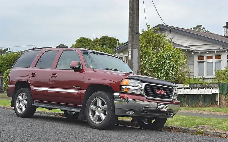
Common on this vehicle:Warning lightNoiseVibration or shudderLeakLoss of engine power, no accelerationShifting faultCorrosion or rustGauge or instrument fault
Record by record
64 records state a cause or a remedy. Each record is shown as short labels in the order fault → finding the cause → correction. Press a label to narrow to the records that state it.
Component named as the cause
Work done
How it is said to have ended
- says it did not fix it1
A ribbon is as wide as the records that state both of its ends (only the commonest are drawn). A record that names several symptoms or components runs through each. Orange is records that say the fault came back or was not fixed. Results come from owners’ reports only; one that does not say is “result not stated”. None of this is a likelihood of a cause or a rate at which work succeeds.
Read the records one by one (21)
Known issues4L60-E / 4L65-E clunk on 2-3 upshift or 3-2 downshift (normal condition)1
Manufacturer communication2005–2006 GMC YUKON DENALI ・ 2018-05-21
2-3 Upshift and 3-2 Downshift Clunk Normal Condition
1Fault
- A clunk noise can be heard on a 2-3 upshift or a 3-2 downshift.
- The condition may be more pronounced on a 4-wheel drive vehicle because of the additional tolerances in the transfer case.
2Finding the cause
Possible causes
- During a 2-3 upshift the 2-4 band is released and the 3-4 clutch is applied; the timing of this shift can momentarily reverse the torque on the output shaft, which makes the clunk.
- The same torque reversal can occur on a 3-2 downshift, when the 3-4 clutch is released and the 2-4 band applied.
3Correction
Caution
- For 2005 model year fullsize utilities and pickups, refer to Corporate Bulletin Number 05-07-30-012.
- This is a normal condition; no repairs should be attempted.
Read the sentences of the record
From the manufacturer’s document
- Applies to:Applies to 2014 and prior GM passenger cars and light duty trucks with the 4L60-E, 4L65-E or 4L70-E automatic transmission (RPOs M30, M32, M70).
- Caution:For 2005 model year fullsize utilities and pickups, refer to Corporate Bulletin Number 05-07-30-012.
- Condition:A clunk noise can be heard on a 2-3 upshift or a 3-2 downshift.
- Cause:During a 2-3 upshift the 2-4 band is released and the 3-4 clutch is applied; the timing of this shift can momentarily reverse the torque on the output shaft, which makes the clunk.
- Cause:The same torque reversal can occur on a 3-2 downshift, when the 3-4 clutch is released and the 2-4 band applied.
- Condition:The condition may be more pronounced on a 4-wheel drive vehicle because of the additional tolerances in the transfer case.
- Caution:This is a normal condition; no repairs should be attempted.
Open the manufacturer’s document (PDF) ↗ The points above were read from this document.
- Remedy
- This information was created to inform the technician that the 2-3 upshift and the 3-2 downshift clunk is caused by the releasing of the 2-4 band and application of the 3-4 clutch assembly during an upshift. Also during a 3-2 downshift, the releasing of the 3-4 clutch during the application of the 2-4 band, can cause torque reversal down the output shaft creating a clunk. This is a normal condition.
Known issuesGrind / ratchet noise when shifting into Park in 4LO (characteristic)1
Manufacturer communication2000–2006 GMC YUKON DENALI ・ 2018-08-20
Light Duty Trucks: Grinding Noise in Park with 4WD Low
1Fault
- Light duty trucks with automatic transmission and 4 wheel drive may make a grinding/ratcheting noise when the transmission is shifted into park while the transfer case is in 4 wheel drive low (4LO) range.
- The grind/ratchet noise lasts approximately one second.
2Finding the cause
Possible causes
- When the transmission is shifted from drive or reverse into park with the transfer case in 4LO, the driveline unloads and turns the propeller shaft approximately 1/8 of a turn.
- The gear reduction in the transfer case makes the transmission output shaft turn faster than the parking pawl will hold, so the parking pawl grinds/ratchets until the output shaft stops.
3Correction
Caution
- This should be considered characteristic of 4 wheel drive vehicles operated in 4LO.
- Replacing transmission, transfer case and/or driveline components will not resolve the concern; shifting into park with the transfer case in the 4HI or 2HI range is recommended.
Read the sentences of the record
From the manufacturer’s document
- Applies to:The model list names GMC Yukon models, 1999 - 2019.
- Condition:Light duty trucks with automatic transmission and 4 wheel drive may make a grinding/ratcheting noise when the transmission is shifted into park while the transfer case is in 4 wheel drive low (4LO) range.
- Cause:When the transmission is shifted from drive or reverse into park with the transfer case in 4LO, the driveline unloads and turns the propeller shaft approximately 1/8 of a turn.
- Cause:The gear reduction in the transfer case makes the transmission output shaft turn faster than the parking pawl will hold, so the parking pawl grinds/ratchets until the output shaft stops.
- Condition:The grind/ratchet noise lasts approximately one second.
- Caution:This should be considered characteristic of 4 wheel drive vehicles operated in 4LO.
- Caution:Replacing transmission, transfer case and/or driveline components will not resolve the concern; shifting into park with the transfer case in the 4HI or 2HI range is recommended.
Open the manufacturer’s document (PDF) ↗ The points above were read from this document.
- Remedy
- This Preliminary information communicates to the dealer technician thatLight Duty Trucks equipped with automatic transmissions and 4 wheel drive may exhibit a condition of grinding/ratcheting type noise when shifting the automatic transmission into park while the transfer case is in 4 wheel drive low (4LO) range. Dealers technician's are advised this condition should be deemed a normal characteristic of 4WD low operation.
ENGINE AND ENGINE COOLING6
Manufacturer communication2005–2006 GMC YUKON DENALI ・ 2024-02-17(6 earlier editions of this document folded here)
Warranty Admin Service Bulletin - Engine/Transmission Replacement
1Fault
- Under GM Service Policies and Procedures, dealers are to perform the most cost economical repair when deciding between assembly repair and replacement.
2Finding the cause
Not stated
3Correction
Read the sentences of the record
From the manufacturer’s document
- Applies to:Applies to GM passenger cars and light duty trucks in Canada, model years 2005 to 2025.
- Condition:Under GM Service Policies and Procedures, dealers are to perform the most cost economical repair when deciding between assembly repair and replacement.
Open the manufacturer’s document (PDF) ↗ The points above were read from this document.
- Remedy
- This Warranty Admin service bulletin provides guidelines for Dealers Not Required and for Dealers Required to Contact the PQC for engine or transmission assembly replacement and explains the PQC process, GWM Transaction submission, vehicle service record retention and proper handling of assembly returns for Canadian Dealers only.
Manufacturer communication2000–2006 GMC YUKON DENALI ・ 2024-02-02
1Fault
Not stated
2Finding the cause
Steps to confirm (in the document’s order)
- Refer to the Engine Mechanical Specification in SI for the correct bore and piston specification.
3Correction
Repair
- When installing a piston into a cylinder, use a ring compressor sleeve or equivalent for best results.
- Choose a sleeve with a smooth radius that tapers down to the specific bore size.
- Select a size only slightly bigger than the piston diameter and not larger than the cylinder bore diameter.
Caution
- If a sleeve is unavailable in the needed size, a universal ring compressor will work but is more difficult to use.
Read the sentences of the record
From the manufacturer’s document
- Applies to:Applies to 2024 and earlier GM passenger cars and trucks.
- Repair:When installing a piston into a cylinder, use a ring compressor sleeve or equivalent for best results.
- Repair:Choose a sleeve with a smooth radius that tapers down to the specific bore size.
- Repair:Select a size only slightly bigger than the piston diameter and not larger than the cylinder bore diameter.
- Confirm:Refer to the Engine Mechanical Specification in SI for the correct bore and piston specification.
- Caution:If a sleeve is unavailable in the needed size, a universal ring compressor will work but is more difficult to use.
Open the manufacturer’s document (PDF) ↗ The points above were read from this document.
- Remedy
- This PI bulletin advises the technician on the proper way to install the pistons in an engine.
Manufacturer communication2004–2006 GMC YUKON DENALI ・ 2023-11-22
Vibration Analysis Worksheet Service Bulletin
1Fault
2Finding the cause
Steps to confirm (in the document’s order)
- When diagnosing vibration, use the worksheet together with the Vibration Analysis - Road Testing procedure in the service information.
- Place the sensor where the vibration is felt: on the seat track for a seat complaint, on the steering column for a steering wheel complaint.
- Moving the sensor to other areas, look for the same Hz reading with the greatest amplitude.
- If a system balance was attempted and the vibration remains, check ring gear backlash at each tooth; readings should not vary more than 0.050 mm (0.002 in).
- Aluminum wheel/tire runout measured on the vehicle: maximum 0.030 in (.762 mm).
3Correction
Read the sentences of the record
From the manufacturer’s document
- Applies to:Applies to 2024 and prior GM passenger cars and trucks.
- Confirm:When diagnosing vibration, use the worksheet together with the Vibration Analysis - Road Testing procedure in the service information.
- Confirm:Place the sensor where the vibration is felt: on the seat track for a seat complaint, on the steering column for a steering wheel complaint.
- Confirm:Moving the sensor to other areas, look for the same Hz reading with the greatest amplitude.
- Confirm:If a system balance was attempted and the vibration remains, check ring gear backlash at each tooth; readings should not vary more than 0.050 mm (0.002 in).
- Confirm:Aluminum wheel/tire runout measured on the vehicle: maximum 0.030 in (.762 mm).
- Confirm:Hub mounting surface runout: maximum 0.005 in (0.132 mm).
- Confirm:Wheel stud runout: maximum 0.010 in (0.254 mm).
Open the manufacturer’s document (PDF) ↗ The points above were read from this document.
- Remedy
- This service bulletin provides a vibration analysis worksheet the technician can use in conjunction with the appropriate Vibration Analysis-Road testing procedure when diagnosing vibration concerns.
Manufacturer communication2000–2006 GMC YUKON DENALI ・ 2023-09-26
Normal Transmission Shift and Throttle Response Delay
1Fault
- A sag or hesitation may be noticed when coasting at low speeds of less than 24 km/h (15 mph) with a closed throttle and then aggressively applying the throttle.
- With an automatic transmission, after a hard complete stop with a closed throttle immediately followed by an aggressive throttle opening, the downshifts may not be completed by the time the throttle is opened.
- A sag or hesitation may also be noticed while cruising at highway speeds and then aggressively increasing the throttle, forcing a down-shift.
2Finding the cause
Possible causes
- In this maneuver the throttle blade is opened slowly for up to 0.7 seconds, even though the accelerator is applied aggressively, to help minimize driveline lash and clunking.
- As a result, approximately 0.5 seconds of zero torque may be commanded to allow the shift to first gear to occur.
3Correction
Caution
- All of these conditions are a result of Torque Management and should be considered normal; no repairs should be attempted.
Read the sentences of the record
From the manufacturer’s document
- Applies to:GM passenger cars and trucks, model years 2000 to 2024.
- Condition:A sag or hesitation may be noticed when coasting at low speeds of less than 24 km/h (15 mph) with a closed throttle and then aggressively applying the throttle.
- Cause:In this maneuver the throttle blade is opened slowly for up to 0.7 seconds, even though the accelerator is applied aggressively, to help minimize driveline lash and clunking.
- Condition:With an automatic transmission, after a hard complete stop with a closed throttle immediately followed by an aggressive throttle opening, the downshifts may not be completed by the time the throttle is opened.
- Cause:As a result, approximately 0.5 seconds of zero torque may be commanded to allow the shift to first gear to occur.
- Condition:A sag or hesitation may also be noticed while cruising at highway speeds and then aggressively increasing the throttle, forcing a down-shift.
- Caution:All of these conditions are a result of Torque Management and should be considered normal; no repairs should be attempted.
Open the manufacturer’s document (PDF) ↗ The points above were read from this document.
- Remedy
- The service bulletin advises the tech of a normal transmission shift condition and the delay in throttle response when the throttle plate is opened rapidly and advises the customer that it is normal for the delay.
Manufacturer communication2005–2006 GMC YUKON DENALI ・ 2022-12-06(2 earlier editions of this document folded here)
Engine and Transmission Assembly Replacement Under Warranty Policy
1Fault
- The document gives the policies for U.S. dealers on engine and transmission assembly replacement under warranty, policy or Customer Enthusiasm.
2Finding the cause
Not stated
3Correction
Read the sentences of the record
From the manufacturer’s document
- Applies to:Applies to GM passenger cars and light duty trucks (U.S. only), model years 2005 to 2023.
- Condition:The document gives the policies for U.S. dealers on engine and transmission assembly replacement under warranty, policy or Customer Enthusiasm.
Open the manufacturer’s document (PDF) ↗ The points above were read from this document.
- Remedy
- This bulletin provides information on Policies Applicable to All U.S. Dealers for Engine and Transmission Assembly Replacement Under Warranty, Policy or Customer Enthusiasm and information on Submission of Warranty Transaction in Global Warranty Management.
Manufacturer communication2003–2006 GMC YUKON DENALI ・ 2022-10-11(1 earlier editions of this document folded here)
OEM and Remanufactured Engine/Transmission ID Notification
1Fault
Not stated
2Finding the cause
Steps to confirm (in the document’s order)
- The engine bar code tag could be on a rocker arm cover, on the ends of a cylinder head, or on the oil pan or oil rail area of the engine.
- All remanufactured engines have a label on the right or left side of the block.
- On the 4.8L/5.3L/6.0L/6.2L (Gen III/Gen IV) engines the remanufactured engine label is on the left side of the block.
3Correction
Caution
- If a piston must be replaced, measure the cylinder before ordering; most of these engines have oversized cylinders, and oversized piston ring packs are not available for service.
- If crankshaft bearings must be replaced, measure the crankshaft before ordering; a crankshaft that has been turned must be replaced, together with all new standard size bearings.
Read the sentences of the record
From the manufacturer’s document
- Applies to:Applies to 2003–2023 GM passenger cars and trucks.
- Confirm:The engine bar code tag could be on a rocker arm cover, on the ends of a cylinder head, or on the oil pan or oil rail area of the engine.
- Confirm:All remanufactured engines have a label on the right or left side of the block.
- Confirm:On the 4.8L/5.3L/6.0L/6.2L (Gen III/Gen IV) engines the remanufactured engine label is on the left side of the block.
- Caution:If a piston must be replaced, measure the cylinder before ordering; most of these engines have oversized cylinders, and oversized piston ring packs are not available for service.
- Caution:If crankshaft bearings must be replaced, measure the crankshaft before ordering; a crankshaft that has been turned must be replaced, together with all new standard size bearings.
Open the manufacturer’s document (PDF) ↗ The points above were read from this document.
- Remedy
- This service bulletin provides information on OEM and Remanufactured Engine and Automatic Transmission/Transaxle Identification.
POWER TRAIN5
Manufacturer communication2000–2006 GMC YUKON DENALI ・ 2024-08-15
Transmission Core Damage Prevention Notice
1Fault
- GM is receiving many cracked or broken transmission cores at the remanufacturing facilities, and the damage makes them unusable for remanufacturing.
2Finding the cause
3Correction
Read the sentences of the record
From the manufacturer’s document
- Applies to:Applies to 2000 to 2024 GM passenger cars, SUVs and light/medium duty trucks.
- Condition:GM is receiving many cracked or broken transmission cores at the remanufacturing facilities, and the damage makes them unusable for remanufacturing.
Open the manufacturer’s document (PDF) ↗ The points above were read from this document.
- Remedy
- GM is receiving damaged (cracked or broken) transmission cores returned to the reman facilities. The damage is being caused either in the removal process by the technician, or inadequate packaging or shipping. This bulletin advises the dealers to be more careful not to damage the transmissions during removal and to package the core properly for return.
Manufacturer communication2005–2006 GMC YUKON DENALI ・ 2024-06-07(4 earlier editions of this document folded here)
Water or Ethylene Glycol in Transmission Fluid
1Fault
- Water or ethylene glycol in ATF changes the friction of the clutches, frequently causing shudder during engagement or gear changes, especially during torque converter clutch engagement.
2Finding the cause
Steps to confirm (in the document’s order)
- An indication of water in the ATF: ATF blowing out of the transmission vent tube.
- The ATF may appear cloudy or, with extreme contamination, look like a strawberry milkshake.
- There may be visible water in the oil pan or a milky white substance inside the pan area.
- Spacer plate gaskets appear swollen or wrinkled in areas where they are not compressed.
- If water is found in the ATF and its source is not identified, or a leaking in-radiator transmission oil cooler is suspected, a simple and quick test kit that detects ethylene glycol in ATF is available.
3Correction
Repair
- If water or coolant is found in the transmission, all rubber-type seals, all composition-faced clutch plates and/or bands, all nylon parts and the torque converter must be replaced.
- Thoroughly clean and rebuild the transmission, using new gaskets and oil filter.
- Flush and flow check the transmission oil cooler using J-45096.
- Thoroughly inspect the engine cooling system and hoses and clean/repair as necessary.
Read the sentences of the record
From the manufacturer’s document
- Applies to:Applies to 2025 and prior GM passenger cars and trucks equipped with an automatic transmission.
- Condition:Water or ethylene glycol in ATF changes the friction of the clutches, frequently causing shudder during engagement or gear changes, especially during torque converter clutch engagement.
- Confirm:An indication of water in the ATF: ATF blowing out of the transmission vent tube.
- Confirm:The ATF may appear cloudy or, with extreme contamination, look like a strawberry milkshake.
- Confirm:There may be visible water in the oil pan or a milky white substance inside the pan area.
- Confirm:Spacer plate gaskets appear swollen or wrinkled in areas where they are not compressed.
- Confirm:If water is found in the ATF and its source is not identified, or a leaking in-radiator transmission oil cooler is suspected, a simple and quick test kit that detects ethylene glycol in ATF is available.
- Confirm:Obtain the Gly-Tek test kit from the Nelco Company and test the ATF to decide accurately whether the radiator needs to be replaced.
- Repair:If water or coolant is found in the transmission, all rubber-type seals, all composition-faced clutch plates and/or bands, all nylon parts and the torque converter must be replaced.
- Repair:Thoroughly clean and rebuild the transmission, using new gaskets and oil filter.
- Repair:Flush and flow check the transmission oil cooler using J-45096.
- Repair:Thoroughly inspect the engine cooling system and hoses and clean/repair as necessary.
Open the manufacturer’s document (PDF) ↗ The points above were read from this document.
- Remedy
- This bulletin provides information on the harmful effects of water or ethylene glycol in transmission fluid.
Manufacturer communication2000–2006 GMC YUKON ・ 2022-10-17
Torque Converter Bolt Removal Warning
1Fault
- Noise from underneath a vehicle equipped with an automatic transmission.
2Finding the cause
Possible causes
- Running the engine with those bolts removed may damage the pilot on the front of the torque converter, the pilot hole in the end of the crankshaft, or both.
Steps to confirm (in the document’s order)
- Use chassis ears to isolate the component or assembly that is the loudest source of the noise.
3Correction
Caution
- Do not remove the flex plate to torque converter bolts, push the converter back toward the transmission and start the engine to tell whether the noise is from the engine or the transmission.
Read the sentences of the record
From the manufacturer’s document
- Applies to:All brands and models, model years 2000 - 2021.
- Condition:Noise from underneath a vehicle equipped with an automatic transmission.
- Caution:Do not remove the flex plate to torque converter bolts, push the converter back toward the transmission and start the engine to tell whether the noise is from the engine or the transmission.
- Cause:Running the engine with those bolts removed may damage the pilot on the front of the torque converter, the pilot hole in the end of the crankshaft, or both.
- Confirm:Use chassis ears to isolate the component or assembly that is the loudest source of the noise.
Open the manufacturer’s document (PDF) ↗ The points above were read from this document.
- Remedy
- This Preliminary Information communication provides information to the technician to not remove the torque converter bolts and start the engine as this may cause damage to the torque converter of the crankshaft on vehicles equipped with an automatic transmission.
Manufacturer communication2000–2006 GMC YUKON DENALI ・ 2022-09-19
Flexplate and Torque Converter Separation Warning
1Fault
- A noise comes from underneath a vehicle equipped with an automatic transmission.
- The technician may find that the noise comes from the bell housing area.
2Finding the cause
Possible causes
- Running the engine with those bolts removed may damage the pilot on the front of the torque converter, the pilot hole in the end of the crankshaft, or both.
Steps to confirm (in the document’s order)
- Use chassis ears to isolate the component or assembly that is the loudest source of the noise.
3Correction
Caution
- Do not separate the torque converter from the flex plate.
- Do not remove the flex plate to torque converter bolts, push the converter back and start the engine to tell whether the noise is from the engine or the transmission.
Read the sentences of the record
From the manufacturer’s document
- Applies to:Applies to GM passenger cars and trucks, model years 2000 to 2023.
- Condition:A noise comes from underneath a vehicle equipped with an automatic transmission.
- Condition:The technician may find that the noise comes from the bell housing area.
- Caution:Do not separate the torque converter from the flex plate.
- Caution:Do not remove the flex plate to torque converter bolts, push the converter back and start the engine to tell whether the noise is from the engine or the transmission.
- Cause:Running the engine with those bolts removed may damage the pilot on the front of the torque converter, the pilot hole in the end of the crankshaft, or both.
- Confirm:Use chassis ears to isolate the component or assembly that is the loudest source of the noise.
Open the manufacturer’s document (PDF) ↗ The points above were read from this document.
- Remedy
- This diagnostic tip advises the tech not to separate the flexplate from the torque convertor or damage my occur if the engine is started while diagnosing for noise from the engine or transmission.
Manufacturer communication2006 GMC YUKON DENALI ・ 2017-12-22
Proper Wheel Installation and Torque Techniques
1Fault
- Vibration may be felt in the steering wheel or seat, centered at 10-14 Hz, between 93-115 km/h (58-72 mph).
2Finding the cause
Possible causes
- Inappropriate wheel torque methods may leave the wheel and tire assembly offset when mounted.
3Correction
Repair
- Remove the tire and wheel assemblies, index them at least two stud positions from the previous position, and re-install them.
- Step 1: with the wheel off the ground, install all lug nuts hand tight using only a socket.
- Step 2: snug all lug nuts in a star or criss-cross pattern with a hand wrench.
- Step 3: lower the vehicle until there is just enough contact to resist, then torque to specification with a torque wrench.
Caution
- This first order tire/wheel vibration may be misdiagnosed as assembly imbalance or excessive tire Radial Force Variation.
- Improper torque may distort the brake rotor and vary the wheel mounting, which can cause smooth road shake.
- Do not use torque sticks or an impact driver to tighten wheel lug nuts.
Read the sentences of the record
From the manufacturer’s document
- Applies to:Applies to 2006-2013 GM passenger cars and light duty trucks.
- Condition:Vibration may be felt in the steering wheel or seat, centered at 10-14 Hz, between 93-115 km/h (58-72 mph).
- Cause:Inappropriate wheel torque methods may leave the wheel and tire assembly offset when mounted.
- Caution:This first order tire/wheel vibration may be misdiagnosed as assembly imbalance or excessive tire Radial Force Variation.
- Caution:Improper torque may distort the brake rotor and vary the wheel mounting, which can cause smooth road shake.
- Repair:Remove the tire and wheel assemblies, index them at least two stud positions from the previous position, and re-install them.
- Caution:Do not use torque sticks or an impact driver to tighten wheel lug nuts.
- Repair:Step 1: with the wheel off the ground, install all lug nuts hand tight using only a socket.
- Repair:Step 2: snug all lug nuts in a star or criss-cross pattern with a hand wrench.
- Repair:Step 3: lower the vehicle until there is just enough contact to resist, then torque to specification with a torque wrench.
Open the manufacturer’s document (PDF) ↗ The points above were read from this document.
- Remedy
- This informational bulletin provides a description of the proper wheel installation and proper wheel torque techniques used to install wheels onto vehicles
ENGINE4
Manufacturer communication2003–2006 GMC YUKON DENALI ・ 2021-04-20
Engine and Transmission Identification
1Fault
Not stated
2Finding the cause
Not stated
3Correction
OEM and Remanufactured Engine and Automatic Transmission/Transaxle Identification
Read the sentences of the record
- Remedy
- OEM and Remanufactured Engine and Automatic Transmission/Transaxle Identification
Manufacturer communication2006 GMC YUKON DENALI ・ 2018-05-29(1 earlier editions of this document folded here)
Service Information Bulletin: Assembly Replacement vs. Repair Process
1Fault
- All service agents must still contact the PQC for Allison transmission replacement, specified Duramax diesel engine replacement and any current restrictions or exchanges.
2Finding the cause
Not stated
3Correction
Read the sentences of the record
From the manufacturer’s document
- Applies to:Applies to 2015 and prior GM passenger cars and light duty trucks with CNG, LPG or gasoline engine, automatic or manual transmission and/or transfer case.
- Condition:All service agents must still contact the PQC for Allison transmission replacement, specified Duramax diesel engine replacement and any current restrictions or exchanges.
Open the manufacturer’s document (PDF) ↗ The points above were read from this document.
- Remedy
- This informational bulletin provides a process to the service agents that are not required to contact PQC, to determine when to replace a assembly as opposed to repairing and if an engine or transmission is being returned, that it has all the information in relation to that part being returned.
Manufacturer communication2003–2006 GMC YUKON DENALI ・ 2018-05-21
Revision to 01-00-89-010I Adding 2013 Model Year
1Fault
- The bulletin is a reference and strategy document for reducing customer comebacks and buyback situations.
2Finding the cause
Not stated
3Correction
This informational bulletin provides a revision for 01-00-89-010I to add the 2013 model year.
Read the sentences of the record
From the manufacturer’s document
- Applies to:Applies to 2013 and prior GM passenger cars and trucks.
- Condition:The bulletin is a reference and strategy document for reducing customer comebacks and buyback situations.
Open the manufacturer’s document (PDF) ↗ The points above were read from this document.
- Remedy
- This informational bulletin provides a revision for 01-00-89-010I to add the 2013 model year.
Manufacturer communication2006 GMC YUKON DENALI ・ 2018-04-23
Non-GM Engine and Transmission Calibration Tampering Information
1Fault
Not stated
2Finding the cause
Not stated
3Correction
Repair
- GM requires retrieving the calibration information and performing the Calibration Verification Procedure when a hard part failure inside the engine is suspected, before disassembly, repair or replacement of an engine assembly under warranty.
Read the sentences of the record
From the manufacturer’s document
- Applies to:Applies to 2006-2014 GM passenger cars and light duty trucks with any V8 gasoline engine.
- Repair:GM requires retrieving the calibration information and performing the Calibration Verification Procedure when a hard part failure inside the engine is suspected, before disassembly, repair or replacement of an engine assembly under warranty.
Open the manufacturer’s document (PDF) ↗ The points above were read from this document.
- Remedy
- This informational bulletin provides information of suspected tampering or vehicle modifications for non-GM (Aftermarket) engine and transmission calibrations for V6 and V8 gasoline engines Using Tech 2î or global diagnostic system 2 (GDS 2)
ELECTRICAL SYSTEM2
Manufacturer communication2006 GMC YUKON DENALI ・ 2020-12-07(1 earlier editions of this document folded here)
Aftermarket ALDL/DLC Interface Devices - Diagnostic Concerns
1Fault
- Gauge or instrument fault
- Warning light
- C0561 (general documents only)
- U0100 (general documents only)
- U0101 (general documents only)
- U186B (general documents only)
- U1862 (general documents only)
- The radio may not shut off after the vehicle is shut down, and bus or LAN traffic may stay active, leading to a discharged battery.
- C0561 may be stored in the EBCM, leading to a traction control issue, and there may be no high speed LAN communication with various communication U-codes.
- The SES, MIL or CEL light may be set with numerous communication DTCs such as U0100, U0101, U186B and U1862.
- The transmission may not shift for one key cycle (TCM in default mode), and gauge readings may be erratic or displays may flicker.
2Finding the cause
Possible causes
- Monitoring devices and other electronic accessories such as aftermarket cruise control or police speed checking devices (RADAR or LIDAR) may cause one or more of the listed concerns.
- Many of the problems could be caused by an open connection on the HSCAN bus: a device that connects to only one CAN + causes bus errors and erratic ECU behavior.
Steps to confirm (in the document’s order)
- If normal diagnostics find no root cause, check for a device plugged into the ALDL or Data Link Connector (DLC) for tracking and/or maintenance interval scheduling.
3Correction
Repair
- If SI diagnostics do not identify the source and the device is available, try to duplicate the condition, then remove the device to see whether the condition is eliminated.
- If removing the DLC interface device resolves the concern, tell the customer the result and that they should work with the device's supplier for further resolution.
Caution
- The customer may remove the device for use in another vehicle while theirs is in for service.
- Some devices carry a second DLC connector, with the device and the rest of the harness hidden out of sight, so the technician may not notice that the diagnostic connector is not in the factory location.
Read the sentences of the record
From the manufacturer’s document
- Applies to:Applies to 2021 and earlier GM passenger cars and trucks.
- Condition:The radio may not shut off after the vehicle is shut down, and bus or LAN traffic may stay active, leading to a discharged battery.
- Condition:C0561 may be stored in the EBCM, leading to a traction control issue, and there may be no high speed LAN communication with various communication U-codes.
- Condition:The SES, MIL or CEL light may be set with numerous communication DTCs such as U0100, U0101, U186B and U1862.
- Condition:The transmission may not shift for one key cycle (TCM in default mode), and gauge readings may be erratic or displays may flicker.
- Confirm:If normal diagnostics find no root cause, check for a device plugged into the ALDL or Data Link Connector (DLC) for tracking and/or maintenance interval scheduling.
- Cause:Monitoring devices and other electronic accessories such as aftermarket cruise control or police speed checking devices (RADAR or LIDAR) may cause one or more of the listed concerns.
- Cause:Many of the problems could be caused by an open connection on the HSCAN bus: a device that connects to only one CAN + causes bus errors and erratic ECU behavior.
- Caution:The customer may remove the device for use in another vehicle while theirs is in for service.
- Caution:Some devices carry a second DLC connector, with the device and the rest of the harness hidden out of sight, so the technician may not notice that the diagnostic connector is not in the factory location.
- Repair:If SI diagnostics do not identify the source and the device is available, try to duplicate the condition, then remove the device to see whether the condition is eliminated.
- Repair:If removing the DLC interface device resolves the concern, tell the customer the result and that they should work with the device's supplier for further resolution.
Open the manufacturer’s document (PDF) ↗ The points above were read from this document.
- Remedy
- The intent of this technical bulletin is to identify aftermarket ALDL or DLC interface devices as potential sources for causing multiple customer concerns that do not have other diagnostic methods to identify them.
Manufacturer communication2005–2006 GMC YUKON DENALI ・ 2018-05-21
Throttle Position Sensor Cover Replacement
1Fault
- Loss of engine power, no acceleration
- Warning light
- Check engine / Service Engine Soon
- Reduced Engine Power
- P2135
- P1516
- P2101
- P2176
- The malfunction indicator lamp (MIL) is illuminated with a Reduced Engine Power message displayed.
- A scan tool may show DTC P2135: Throttle Position (TP) Sensor 1-2 Correlation set as Current or in History.
2Finding the cause
Possible causes
- The condition may be caused by the difference between TP Sensor 1 and TP Sensor 2 exceeding a calibrated value for more than 2 seconds.
Steps to confirm (in the document’s order)
- After installing the new cover, if the scan tool TP Sensor 1 and 2 Agree/Disagree parameter displays Disagree, replace the throttle body assembly.
- If DTC P1516, P2101 and/or P2176 are set, replace the throttle body.
3Correction
Repair
- Clean the throttle body bore and throttle plate with a clean shop towel and GM Top Engine Cleaner, P/N 1052626 (in Canada, P/N 993026), or ACDelco Upper Engine and Fuel Injector Cleaner, P/N 88861803, or an equivalent product.
- Remove the old TP sensor cover from the throttle body: grasp the cover, carefully lift it up and separate it from the throttle body.
- Tighten the throttle body fasteners to 89 lb in (= 10.1 N·m) (the text prints the metric value as "10 Y").
- Reprogram the ECM using the Service Programming System (SPS) with the latest calibration available on TIS2WEB.
- Perform the Throttle Learn Reset Procedure.
Part numbers printed in the document
88861803Cleaner,Fuel Injector & Upper Engine Acdelco 16OzLook up at RockAuto (aftermarket candidates) ↗Search the web ↗
Replaced by: 19355198as stated by GMPartsGiant (checked 2026-10-06) ↗Look up at RockAuto (aftermarket candidates) ↗Search the web ↗
The numbers are as the document prints them. The name and the replacing number are what the pages of GMPartsGiant, a reseller of genuine parts and not GM, state. Aftermarket equivalents are not checked here (the links only search by number). Confirm the fit for the vehicle (VIN) before ordering.
Parts
- Part number 19259452, Throttle Position (TP) Sensor Cover, quantity 1.
Part numbers printed in the document
19259452Sensor Kit,Throttle PositionLook up at RockAuto (aftermarket candidates) ↗Search the web ↗
No successor statedas stated by GMPartsGiant (checked 2026-10-06) ↗
The numbers are as the document prints them. The name and the replacing number are what the pages of GMPartsGiant, a reseller of genuine parts and not GM, state. Aftermarket equivalents are not checked here (the links only search by number). Confirm the fit for the vehicle (VIN) before ordering.
Caution
- Do not replace the throttle body; follow the procedure in the bulletin instead.
- If the throttle body is dropped at any time during the procedure, abort the procedure and replace it with a new throttle body assembly.
Read the sentences of the record
From the manufacturer’s document
- Applies to:The Yukon entries are 2008-2011 GMC Canyon, Savana, Sierra, Sierra Denali and Yukon models (note: earlier Yukon model years are not listed).
- Condition:The malfunction indicator lamp (MIL) is illuminated with a Reduced Engine Power message displayed.
- Condition:A scan tool may show DTC P2135: Throttle Position (TP) Sensor 1-2 Correlation set as Current or in History.
- Cause:The condition may be caused by the difference between TP Sensor 1 and TP Sensor 2 exceeding a calibrated value for more than 2 seconds.
- Caution:Do not replace the throttle body; follow the procedure in the bulletin instead.
- Repair:Clean the throttle body bore and throttle plate with a clean shop towel and GM Top Engine Cleaner, P/N 1052626 (in Canada, P/N 993026), or ACDelco Upper Engine and Fuel Injector Cleaner, P/N 88861803, or an equivalent product.
- Repair:Remove the old TP sensor cover from the throttle body: grasp the cover, carefully lift it up and separate it from the throttle body.
- Caution:If the throttle body is dropped at any time during the procedure, abort the procedure and replace it with a new throttle body assembly.
- Confirm:After installing the new cover, if the scan tool TP Sensor 1 and 2 Agree/Disagree parameter displays Disagree, replace the throttle body assembly.
- Confirm:If DTC P1516, P2101 and/or P2176 are set, replace the throttle body.
- Repair:Tighten the throttle body fasteners to 89 lb in (= 10.1 N·m) (the text prints the metric value as "10 Y").
- Repair:Reprogram the ECM using the Service Programming System (SPS) with the latest calibration available on TIS2WEB.
- Repair:Perform the Throttle Learn Reset Procedure.
- Parts:Part number 19259452, Throttle Position (TP) Sensor Cover, quantity 1.
Open the manufacturer’s document (PDF) ↗ The points above were read from this document.
- Remedy
- This technical bulletin provides a procedure for replacing the throttle position sensor cover for concerns regarding a indicator lamp illuminated reduced power message displayed and DTC P2135 set.
EQUIPMENT2
Manufacturer communication2003–2006 GMC YUKON DENALI ・ 2018-06-04
Automatic Transmission Oil Cooler Flow Test Essential Tool J-45096
1Fault
- In flow mode, an electronic flow meter measures the flow capability of the ATF oil cooling system.
2Finding the cause
Steps to confirm (in the document’s order)
- On the 4L60-E, the cooler feed (exiting the transmission) is the bottom connector and the return (entering the transmission) is the top connector; J-35944-200 may be required.
- On the 4L80-E, the cooler feed is the front connector and the return is the rear connector; J-35944-200 may be required.
3Correction
Repair
- For the flow test and flush procedure, refer to Automatic Transmission Oil Cooler Flushing and Flow Test J-45096 in SI.
Caution
- Insufficient oil flow through the ATF oil cooling system will cause premature transmission failure; the required minimum flow rate depends directly on the supply oil temperature.
- The oil in the supply vessel must be 18°C (65°F) or warmer for the J-45096 to operate.
- Labor operations that remove the transmission for an internal repair or torque converter replacement include time to flow check and flush the transmission oil cooler system.
- A flow test and flush uses between 4.7-7.5 L (5-8 qts) of DEXRON VI transmission fluid.
Read the sentences of the record
From the manufacturer’s document
- Applies to:Applies to 2011 and prior GM passenger cars and light duty trucks with an automatic transmission/transaxle.
- Condition:In flow mode, an electronic flow meter measures the flow capability of the ATF oil cooling system.
- Caution:Insufficient oil flow through the ATF oil cooling system will cause premature transmission failure; the required minimum flow rate depends directly on the supply oil temperature.
- Caution:The oil in the supply vessel must be 18°C (65°F) or warmer for the J-45096 to operate.
- Confirm:On the 4L60-E, the cooler feed (exiting the transmission) is the bottom connector and the return (entering the transmission) is the top connector; J-35944-200 may be required.
- Confirm:On the 4L80-E, the cooler feed is the front connector and the return is the rear connector; J-35944-200 may be required.
- Repair:For the flow test and flush procedure, refer to Automatic Transmission Oil Cooler Flushing and Flow Test J-45096 in SI.
- Caution:Labor operations that remove the transmission for an internal repair or torque converter replacement include time to flow check and flush the transmission oil cooler system.
- Caution:A flow test and flush uses between 4.7-7.5 L (5-8 qts) of DEXRON VI transmission fluid.
Open the manufacturer’s document (PDF) ↗ The points above were read from this document.
- Remedy
- This informational bulletin provides information for Automatic Transmission Oil Cooler Flow Test Essential Tool J-45096 TransFlow.
Manufacturer communication2005–2006 GMC YUKON DENALI ・ 2018-06-04
Informational Bulletin Revision 09-07-30-018C
1Fault
- A revised process is being implemented for automatic transmission internal repair claim documentation and warranty claim submission.
2Finding the cause
Not stated
3Correction
Read the sentences of the record
From the manufacturer’s document
- Applies to:2014 and prior GM passenger cars and trucks.
- Condition:A revised process is being implemented for automatic transmission internal repair claim documentation and warranty claim submission.
Open the manufacturer’s document (PDF) ↗ The points above were read from this document.
- Remedy
- This informational bulletin provides a revision for 09-07-30-018C to add the 2014 model year and update the Labor Operation.
Showing 21 of the 64 you can open. Narrow the search to see the rest.