
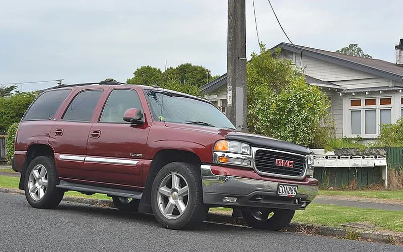
GMC Yukon 2000–2006
Common on this vehicle:Warning lightNoiseLoss of engine power, no accelerationMisfire or rough idleLeakGauge or instrument faultStalls or shuts offDoes not start
Record by record
65 records state a cause or a remedy. Each record is shown as short labels in the order fault → finding the cause → correction. Press a label to narrow to the records that state it.
Symptom
Component named as the cause
Work done
How it is said to have ended
- says it held for a while3
- says it came back2
- says it did not fix it4
A ribbon is as wide as the records that state both of its ends (only the commonest are drawn). A record that names several symptoms or components runs through each. Orange is records that say the fault came back or was not fixed. Results come from owners’ reports only; one that does not say is “result not stated”. None of this is a likelihood of a cause or a rate at which work succeeds.
Read the records one by one (17)
Known issuesSingle-cylinder misfire (P0300-P0308) and/or chirp, squeak or tick at camshaft speed: worn cam lobe / lifter, valve or valve spring2
Manufacturer communication2002–2006 GMC YUKON DENALI ・ 2023-05-06(3 earlier editions of this document folded here)
Diagnostic tip: valve, lifter or camshaft issue
1Fault
- Misfire, chirp, squeak, squeal or tick noise, or MIL illuminated.
- DTCs P0300 (engine misfire detected) and P0301 through P0308 (misfire detected on cylinders 1 through 8) are listed.
2Finding the cause
Possible causes
- Possible causes: worn camshaft lobe and/or lifter roller, a sticking valve, valve leakage, a broken valve spring, or a collapsed AFM lifter.
Steps to confirm (in the document’s order)
- A verified noise is not eliminated by canceling fuel injectors and occurs at camshaft speed (half of crankshaft speed).
- If applying pressure to the valve side of the rocker changes the noise, a lifter and/or cam lobe concern on that cylinder is most likely.
- Disconnect the coils and injectors on one bank, run the engine with that valve cover removed, back off the rocker arm a couple of turns and listen for a change in the noise.
- Measure cam lobe lift at the pushrod side of the rocker arm and compare with other rockers on the same bank; the misfiring or ticking cylinder should have clearly less lift.
- A good indicator of a sticking valve is misfires that keep counting on an aggressive deceleration with engine braking.
3Correction
Repair
- If a worn camshaft lobe or lifter roller is found, replace the camshaft and all lifters, and the plastic lifter guide for the affected lifter.
Caution
- A damaged cam lobe is easy to overlook through the lifter bores, and unworn lifter rollers do not mean the cam lobes are okay; inspect both carefully.
Read the sentences of the record
From the manufacturer’s document
- Applies to:Applies to GM passenger cars and trucks, 2002 through 2023, with V6/V8 pushrod engines.
- Condition:Misfire, chirp, squeak, squeal or tick noise, or MIL illuminated.
- Condition:DTCs P0300 (engine misfire detected) and P0301 through P0308 (misfire detected on cylinders 1 through 8) are listed.
- Confirm:A verified noise is not eliminated by canceling fuel injectors and occurs at camshaft speed (half of crankshaft speed).
- Cause:Possible causes: worn camshaft lobe and/or lifter roller, a sticking valve, valve leakage, a broken valve spring, or a collapsed AFM lifter.
- Confirm:If applying pressure to the valve side of the rocker changes the noise, a lifter and/or cam lobe concern on that cylinder is most likely.
- Confirm:Disconnect the coils and injectors on one bank, run the engine with that valve cover removed, back off the rocker arm a couple of turns and listen for a change in the noise.
- Confirm:Measure cam lobe lift at the pushrod side of the rocker arm and compare with other rockers on the same bank; the misfiring or ticking cylinder should have clearly less lift.
- Caution:A damaged cam lobe is easy to overlook through the lifter bores, and unworn lifter rollers do not mean the cam lobes are okay; inspect both carefully.
- Repair:If a worn camshaft lobe or lifter roller is found, replace the camshaft and all lifters, and the plastic lifter guide for the affected lifter.
- Confirm:A good indicator of a sticking valve is misfires that keep counting on an aggressive deceleration with engine braking.
- Confirm:A broken valve spring may stay stacked together and be hard to see; lightly push on different places on the springs with a small hammer handle.
Open the manufacturer’s document (PDF) ↗ The points above were read from this document.
- Remedy
- This diagnostic tip bulletin provides additional information on how to diagnose a possible valve, lifter or camshaft issue.
Manufacturer communication2002–2006 GMC YUKON DENALI ・ 2018-11-13
Service Engine Soon Lamp, Misfire, Engine Noise Diagnostic Information
1Fault
- Customers may complain of an SES light, engine misfire, and/or engine noise.
- If the SES light is on, there will be a P0300-P0308 DTC with misfires counting on a single cylinder, which may or may not be felt.
- A verified noise is not eliminated by canceling fuel injectors and occurs at camshaft speed (half of crankshaft speed).
2Finding the cause
- Valve Spring: broken
- Active Fuel Management Lifter: failed
- Valve: defective
- Camshaft Lobe: worn
- Lifter Roller: worn
Possible causes
- If SI diagnosis does not isolate the cause, it may be a worn camshaft lobe and/or lifter roller, a sticking valve, valve leakage, a broken valve spring, or a collapsed AFM (Active Fuel Management) lifter.
Steps to confirm (in the document’s order)
- During the noise, press with a wooden hammer handle on the rocker arms at the valve side, push rod side, and side of the rocker to find which one is making noise.
- If pressure on the valve side of the rocker changes the noise, it is most likely a lifter and/or cam lobe concern on that cylinder.
- Measure the cam lobe lift at the push rod side of the rocker arm.
- A good indicator of a sticking valve is engine misfires that continue to count on an aggressive deceleration with engine braking.
- Release the air pressure from the cylinder and work the valve up and down in the guide while turning it 360 degrees; if any binding is felt, a stem to guide clearance concern exists.
3Correction
Repair
- If a worn camshaft lobe or lifter roller is found, follow SI procedures to replace the camshaft and all lifters.
- Also replace the plastic lifter guide for the lifter that had the damaged cam lobe and/or lifter roller.
- Refer to the latest version of PIP4753 for decarboning instructions.
- If a broken valve spring is found, replace the broken valve spring as necessary.
Caution
- If an AFM lifter concern is suspected, refer to the latest version of PIP4568 for additional information.
Read the sentences of the record
From the manufacturer’s document
- Applies to:Applies to GMC Yukon models, 2002 - 2018, with a V8 engine.
- Condition:Customers may complain of an SES light, engine misfire, and/or engine noise.
- Condition:If the SES light is on, there will be a P0300-P0308 DTC with misfires counting on a single cylinder, which may or may not be felt.
- Condition:A verified noise is not eliminated by canceling fuel injectors and occurs at camshaft speed (half of crankshaft speed).
- Cause:If SI diagnosis does not isolate the cause, it may be a worn camshaft lobe and/or lifter roller, a sticking valve, valve leakage, a broken valve spring, or a collapsed AFM (Active Fuel Management) lifter.
- Confirm:During the noise, press with a wooden hammer handle on the rocker arms at the valve side, push rod side, and side of the rocker to find which one is making noise.
- Confirm:If pressure on the valve side of the rocker changes the noise, it is most likely a lifter and/or cam lobe concern on that cylinder.
- Confirm:Measure the cam lobe lift at the push rod side of the rocker arm.
- Repair:If a worn camshaft lobe or lifter roller is found, follow SI procedures to replace the camshaft and all lifters.
- Repair:Also replace the plastic lifter guide for the lifter that had the damaged cam lobe and/or lifter roller.
- Confirm:A good indicator of a sticking valve is engine misfires that continue to count on an aggressive deceleration with engine braking.
- Confirm:Release the air pressure from the cylinder and work the valve up and down in the guide while turning it 360 degrees; if any binding is felt, a stem to guide clearance concern exists.
- Repair:Refer to the latest version of PIP4753 for decarboning instructions.
- Confirm:Typically, the Cylinder Leakage Test outlined in SI should isolate valve leakage.
- Repair:If a broken valve spring is found, replace the broken valve spring as necessary.
- Caution:If an AFM lifter concern is suspected, refer to the latest version of PIP4568 for additional information.
Open the manufacturer’s document (PDF) ↗ The points above were read from this document.
- Remedy
- This Preliminary Information communication provides information to the technician about vehicles that have a Service Engine Soon Malfunction Indicator Lamp on, engine misfire, and/or engine noise. Technician may find Diagnostic Trouble Codes P0300-P0308. If published Service Information diagnostics does not isolate the cause of this concern technician should check for a worn camshaft lobe and/or lifter roller, a sticking valve, valve leakage, a broken valve spring, and a collapsed active fuel management lifter.
Known issuesP0420 / P0430 on a new or just-replaced catalytic converter (break-in not completed)1
Manufacturer communication2002–2006 GMC YUKON DENALI ・ 2019-04-08(1 earlier editions of this document folded here)
Service Engine Soon Lamp at Low Mileage
1Fault
- An SES light may come on on low mileage vehicles or vehicles that recently had the catalytic converter replaced, with DTCs P0420 and/or P0430 stored.
2Finding the cause
Possible causes
- On a new vehicle, catalytic converter efficiency DTCs P0420 and P0430 are disabled for the first hour of engine run time to allow break-in of the catalytic converter.
- If the engine run time is less than one hour, the battery may have been disconnected, or another vehicle power loss event may have occurred, during vehicle manufacturing.
- If the DTCs set shortly after the catalytic converter is replaced, it may be because the engine run time restrictions are no longer in place since the vehicle is no longer new.
- As a result, the catalytic converter may not have completed a thorough break-in cycle after replacement, possibly resulting in a false DTC P0420 and/or P0430.
Steps to confirm (in the document’s order)
- On a new/low mileage vehicle with these DTCs, use the Tech 2 to verify engine run time on the Engine Hour Meter in the IPC Data Display/Data 1 List.
- Finally, restart the engine and operate the vehicle at the conditions for running the DTC P0420/430 tests, and make sure the vehicle passes them.
3Correction
Repair
- Clear the DTCs and perform the drive cycle given in the document.
- Drive cycle step: drive the vehicle at sustained highway speed for 25 to 30 minutes.
- Drive cycle step: restart the engine and resume highway speed for an additional 10 to 15 minutes.
- If the diagnostics do not pass, perform SI diagnostics and repair as necessary.
Read the sentences of the record
From the manufacturer’s document
- Applies to:Applies to GMC Yukon models, 2002 - 2018, with a V8 engine.
- Condition:An SES light may come on on low mileage vehicles or vehicles that recently had the catalytic converter replaced, with DTCs P0420 and/or P0430 stored.
- Cause:On a new vehicle, catalytic converter efficiency DTCs P0420 and P0430 are disabled for the first hour of engine run time to allow break-in of the catalytic converter.
- Confirm:On a new/low mileage vehicle with these DTCs, use the Tech 2 to verify engine run time on the Engine Hour Meter in the IPC Data Display/Data 1 List.
- Cause:If the engine run time is less than one hour, the battery may have been disconnected, or another vehicle power loss event may have occurred, during vehicle manufacturing.
- Cause:If the DTCs set shortly after the catalytic converter is replaced, it may be because the engine run time restrictions are no longer in place since the vehicle is no longer new.
- Cause:As a result, the catalytic converter may not have completed a thorough break-in cycle after replacement, possibly resulting in a false DTC P0420 and/or P0430.
- Repair:Clear the DTCs and perform the drive cycle given in the document.
- Repair:Drive cycle step: drive the vehicle at sustained highway speed for 25 to 30 minutes.
- Repair:Drive cycle step: restart the engine and resume highway speed for an additional 10 to 15 minutes.
- Confirm:Finally, restart the engine and operate the vehicle at the conditions for running the DTC P0420/430 tests, and make sure the vehicle passes them.
- Repair:If the diagnostics do not pass, perform SI diagnostics and repair as necessary.
Open the manufacturer’s document (PDF) ↗ The points above were read from this document.
- Remedy
- This Preliminary Information communication provides information to the technician on the steps to diagnose and repair vehicles that may have a Service Engine Soon Malfunction Indicator Lamp on at low mileage. Technician may find Diagnostic Trouble Codes P0420 and or P0430 stored. Technician should be advised that the catalytic converter efficiency Diagnostic Trouble Codes P0420 and P0430 are disabled for the first hour of engine run time to allow break-in of the catalytic converter. Technician will need to use a Tech2 to check the verify engine run time on the Engine Hour Meter in the Instrument Panel Cluster  Data Display/Data 1 List in the scan tool match. If the engine run time is less than one hour, the battery may have been disconnected, or another vehicle power loss event may have occurred, during vehicle manufacturing. Technician will need to clear the Diagnostic Trouble Codes and perform a drive cycle. If the catalytic converter was replaced and the Diagnostic Trouble Codes set it may be a result of the engine run time restrictions no longer being in place since the vehicle is no longer new. Technician will need to clear the Diagnostic Trouble Codes and perform a drive cycle.
Known issuesReduced Engine Power from throttle body connector crimp, broken wire or grounds1
Owner complaint2004 GMC YUKON DENALI ・ 2013-03-03
Stability control disabled and reduced engine power warnings with 5 MPH speed limit on startup
1Fault
2Finding the cause
Not stated
3Correction
Read the sentences of the record
- Fault
- THE "STABILITY CONTROL DISABLED" SENSOR COMES ON FOLLOWED BY "REDUCED ENGINE POWER" AND MY VEHICLE WON'T GO FASTER THAN 5MPH (= 8.05 km/h). (1 more)
- Remedy
- THEY REPLACED THE "CONNECTOR AT THE THROTTLE BODY" AND CHARGED ME $223.09. (1 more)
- Outcome
- THE ISSUE TEMPORARILY WENT AWAY.
ENGINE4
Owner complaint2003 GMC YUKON DENALI ・ 2013-10-19
Engine and traction control lights illuminating uphill
1Fault
2Finding the cause
Not stated
3Correction
Read the sentences of the record
- Fault
- I WAS DRIVING APPROXIMATELY 65 MPH (= 104.6 km/h) UPHILL WHEN MY ENGINE AND TRACTION LIGHT CAME ON.
- Remedy
- I TOOK THE TRUCK TO A MECHANIC THE NEXT DAY AND HE REPLACED THE THROTTLE BODY.
- Outcome
- I PICKED UP THE TRUCK THAT EVENING AND AS I WAS DRIVING HOME THE SAME THING HAPPENED AGAIN.
Manufacturer communication2000–2006 GMC YUKON DENALI ・ 2024-07-16(2 earlier editions of this document folded here)
Fuel Injection Cleaner Kit Service Bulletin
1Fault
- Hard start or long crank
- Misfire or rough idle
- Does not start
- Warning light
- Check engine / Service Engine Soon
- P0300
- P0301
- P0302
- P0303
- P0304
- P0305
- Rough idle, crank no start, extended crank or misfire, with the engine warning lamp on and DTC P0300, P0301, P0302, P0303, P0304, P0305, P0306, P0307 or P0308 set.
- When the engine is cold, compression on multiple cylinders may be zero.
- The engine may pop through the intake or exhaust while cranking, and the spark plugs may be fuel fouled.
2Finding the cause
Possible causes
- Major carbon build-up on the intake and/or exhaust valves from fuel contamination or incomplete burning of the fuel; misfires should not appear before at least 8,000 km (5,000 mi).
3Correction
Repair
- If there is no valve damage and no cam follower out of place, perform the cleaning procedure to free sticking valves and remove carbon from the valves and pistons.
- If valves are damaged or cam followers are out of place, make the engine mechanical repairs first and then perform the cleaning procedure to prevent a return.
- Fill Cleaner Kit J-35800-A with about 650 ml (22 oz, 2 cans) of Air Intake, Combustion Chamber Cleaner and set the air pressure at the tool to 260 kPa (40 psi).
- With GDS 2 or a scan tool, command engine idle to 2000 rpm so the engine does not stall.
- With the engine at operating temperature in a well-ventilated area, slowly and carefully induce the cleaner into the engine, taking about 3 minutes.
Parts
- The Top Engine Cleaning Kit (ACDelco Air Intake, Valve and Combustion Chamber Cleaner and ACDelco Fuel System Cleaner 44K) is 19435372 for the U.S. and Canada.
Part numbers printed in the document
19435372MAINTENANCE KIT,FUEL SYSTEM ACDELCO 3-11OZLook up at RockAuto (aftermarket candidates) ↗Search the web ↗
No successor statedas stated by GMPartsGiant (checked 2026-10-06) ↗
The numbers are as the document prints them. The name and the replacing number are what the pages of GMPartsGiant, a reseller of genuine parts and not GM, state. Aftermarket equivalents are not checked here (the links only search by number). Confirm the fit for the vehicle (VIN) before ordering.
Caution
- Inducing too much cleaner at too low an RPM, or stalling the engine with too much cleaner at once, may hydro-lock the engine and bend a connecting rod.
Read the sentences of the record
From the manufacturer’s document
- Applies to:Applies to GM passenger cars and trucks with gasoline engines only, model years 2000 to 2025.
- Condition:Rough idle, crank no start, extended crank or misfire, with the engine warning lamp on and DTC P0300, P0301, P0302, P0303, P0304, P0305, P0306, P0307 or P0308 set.
- Condition:When the engine is cold, compression on multiple cylinders may be zero.
- Condition:The engine may pop through the intake or exhaust while cranking, and the spark plugs may be fuel fouled.
- Cause:Major carbon build-up on the intake and/or exhaust valves from fuel contamination or incomplete burning of the fuel; misfires should not appear before at least 8,000 km (5,000 mi).
- Repair:If there is no valve damage and no cam follower out of place, perform the cleaning procedure to free sticking valves and remove carbon from the valves and pistons.
- Repair:If valves are damaged or cam followers are out of place, make the engine mechanical repairs first and then perform the cleaning procedure to prevent a return.
- Caution:Inducing too much cleaner at too low an RPM, or stalling the engine with too much cleaner at once, may hydro-lock the engine and bend a connecting rod.
- Repair:Fill Cleaner Kit J-35800-A with about 650 ml (22 oz, 2 cans) of Air Intake, Combustion Chamber Cleaner and set the air pressure at the tool to 260 kPa (40 psi).
- Repair:With GDS 2 or a scan tool, command engine idle to 2000 rpm so the engine does not stall.
- Repair:With the engine at operating temperature in a well-ventilated area, slowly and carefully induce the cleaner into the engine, taking about 3 minutes.
- Parts:The Top Engine Cleaning Kit (ACDelco Air Intake, Valve and Combustion Chamber Cleaner and ACDelco Fuel System Cleaner 44K) is 19435372 for the U.S. and Canada.
Open the manufacturer’s document (PDF) ↗ The points above were read from this document.
- Remedy
- This service bulletin advises of a new fuel injection cleaner kit used for decarbonizing the intake valves to correct conditions of rough idle, Crank no start, extended crank or misfire, MIL with DTCs, and explains how Top Tier fuels should be used to reduce carbon build-up.
Manufacturer communication2000–2006 GMC YUKON ・ 2023-09-18(5 earlier editions of this document folded here)
Misfire and DTC Codes Diagnostic Information
1Fault
- With DTC P0300 - P0308 and/or P050D, use GDS and save the freeze frame records.
2Finding the cause
Steps to confirm (in the document’s order)
- Perform the relative compression test in the PICO NVH or Oscilloscope software; SI Document number 5518386 covers the procedure.
- If it passes the relative compression test, the concern is an ignition or fuel delivery issue.
- Check the ignition supply voltage to the ignition module/coil assemblies and also to the fuel injectors.
- Inspect the spark plugs for anything abnormal.
- Note the fuel trim values and on which bank, and compare actual MAF with calculated air flow.
3Correction
Caution
- The injector balance procedure in GDS is only a preliminary test and its results should not decide injector replacement, especially with a low or no flow injector.
Read the sentences of the record
From the manufacturer’s document
- Applies to:All brands and models with gas engines, model years 2000 - 2024.
- Condition:With DTC P0300 - P0308 and/or P050D, use GDS and save the freeze frame records.
- Confirm:Perform the relative compression test in the PICO NVH or Oscilloscope software; SI Document number 5518386 covers the procedure.
- Confirm:If it passes the relative compression test, the concern is an ignition or fuel delivery issue.
- Confirm:Check the ignition supply voltage to the ignition module/coil assemblies and also to the fuel injectors.
- Confirm:Inspect the spark plugs for anything abnormal.
- Caution:The injector balance procedure in GDS is only a preliminary test and its results should not decide injector replacement, especially with a low or no flow injector.
- Confirm:Note the fuel trim values and on which bank, and compare actual MAF with calculated air flow.
- Confirm:Check for a possible fuel quality issue, especially with a cold engine hard start and/or a misfire on all cylinders.
- Confirm:Confirm whether a crankshaft variation learn has been completed and whether there is any abnormal engine noise possibly related to the misfire.
Open the manufacturer’s document (PDF) ↗ The points above were read from this document.
- Remedy
- This Preliminary information communicates information that will need to be provided to TAC to aid in diagnosing if a vehicle comes in with misfire and DTC Codes P0300 - P0308 and/or P050D
Manufacturer communication2000–2006 GMC YUKON DENALI ・ 2017-08-15(1 earlier editions of this document folded here)
Engine Misfire and Rough Idle Malfunction Indicator Lamp
1Fault
- Hard start or long crank
- Misfire or rough idle
- Does not start
- Warning light
- Check engine / Service Engine Soon
- P0300
- P0308
- Customers may complain of a MIL and/or engine misfire, rough idle, extended crank, or crank no start.
- One or more misfire codes (DTC P0300-P0308) are found stored in the ECM.
2Finding the cause
Possible causes
- The condition may result from major carbon build up on the intake and/or exhaust valves due to fuel contamination or incomplete burning of the fuel.
Steps to confirm (in the document’s order)
- With the engine cold, compression on multiple cylinders may read 0 PSI (= 0 kPa).
- The engine may pop through the intake or exhaust while cranking, and the spark plugs may be fuel fouled.
3Correction
Repair
- If there is valve damage or cam followers are out of place, make the mechanical repairs first, then perform the cleaning procedure to keep the concern from returning.
- With the engine at operating temperature, slowly induce a bottle of GM Upper Engine and Fuel Injection Cleaner with RPM held above idle so the engine does not stall (typically around 2,000 RPM).
- Turn the engine off and let the cleaner soak for 2.5 to 3 hours.
- To complete the repair, change the engine oil and filter.
Parts
- Upper Engine and Fuel Injector Cleaner is P/N 88861803 (in Canada, P/N 88861804).
Part numbers printed in the document
88861803Cleaner,Fuel Injector & Upper Engine Acdelco 16OzLook up at RockAuto (aftermarket candidates) ↗Search the web ↗
Replaced by: 19355198as stated by GMPartsGiant (checked 2026-10-06) ↗Look up at RockAuto (aftermarket candidates) ↗Search the web ↗
88861804Cleaner,Fuel Injector & Upper Engine Acdelco .473LLook up at RockAuto (aftermarket candidates) ↗Search the web ↗
Discontinued (no successor stated)(replaces 21992873)as stated by GMPartsGiant (checked 2026-10-06) ↗
The numbers are as the document prints them. The name and the replacing number are what the pages of GMPartsGiant, a reseller of genuine parts and not GM, state. Aftermarket equivalents are not checked here (the links only search by number). Confirm the fit for the vehicle (VIN) before ordering.
Caution
- Inducing too much cleaner at too low an RPM, or stalling the engine with cleaner, may hydro-lock the engine and bend a connecting rod.
Read the sentences of the record
From the manufacturer’s document
- Applies to:Applies to all 2000-2015 light duty trucks with gasoline engines.
- Condition:Customers may complain of a MIL and/or engine misfire, rough idle, extended crank, or crank no start.
- Condition:One or more misfire codes (DTC P0300-P0308) are found stored in the ECM.
- Cause:The condition may result from major carbon build up on the intake and/or exhaust valves due to fuel contamination or incomplete burning of the fuel.
- Confirm:With the engine cold, compression on multiple cylinders may read 0 PSI (= 0 kPa).
- Confirm:The engine may pop through the intake or exhaust while cranking, and the spark plugs may be fuel fouled.
- Repair:If there is valve damage or cam followers are out of place, make the mechanical repairs first, then perform the cleaning procedure to keep the concern from returning.
- Repair:With the engine at operating temperature, slowly induce a bottle of GM Upper Engine and Fuel Injection Cleaner with RPM held above idle so the engine does not stall (typically around 2,000 RPM).
- Repair:Turn the engine off and let the cleaner soak for 2.5 to 3 hours.
- Repair:To complete the repair, change the engine oil and filter.
- Caution:Inducing too much cleaner at too low an RPM, or stalling the engine with cleaner, may hydro-lock the engine and bend a connecting rod.
- Parts:Upper Engine and Fuel Injector Cleaner is P/N 88861803 (in Canada, P/N 88861804).
Open the manufacturer’s document (PDF) ↗ The points above were read from this document.
- Remedy
- This Preliminary Information communication provides information to the technician about vehicles that have a Malfunction Indicator Lamp on or engine misfire, rough idle, extended crank, or crank no start in some cases. Technician will need to perform published Service Information diagnostics. If technician finds carbon an upper engine and valve cleaning should be performed.
ELECTRICAL SYSTEM3
Owner complaint2004 GMC YUKON ・ 2025-03-05
Power loss and shaking while driving at 45 MPH; multiple repairs unsuccessful
1Fault
2Finding the cause
3CorrectionNot repaired
Read the sentences of the record
- Fault
- The contact stated while driving 45 MPH (= 72.4 km/h), the vehicle started losing motive power. (3 more)
- Remedy
- The vehicle was not repaired for the most recent failure.
- Inspection
- The vehicle was taken to an independent mechanic where it was diagnosed with throttle body failure; however, the failure persisted.
- Outcome
- The vehicle was repaired but the failure persisted three more times with different diagnoses.
Manufacturer communication2005–2006 GMC YUKON DENALI ・ 2018-06-04(1 earlier editions of this document folded here)
IP to Body Harness Connector Repair for MIL and DTC P2138
1Fault
- Loss of engine power, no acceleration
- Warning light
- Check engine / Service Engine Soon
- Reduced Engine Power
- P2138
- The engine warning lamp comes on intermittently with a message or indicator showing Reduced Engine Power.
- DTC P2138 (Accelerator Pedal Position (APP) Sensor 1-2 Correlation) is set as current or in history.
2Finding the cause
Possible causes
- Water may have entered the instrument panel (IP) to body harness connector, which carries the APP sensor signals to the ECM/PCM.
Steps to confirm (in the document’s order)
- Verify that no aftermarket equipment is electrically connected to the APP sensor signal or low reference circuits, or to any other ECM/PCM 5V reference or low reference circuit.
- Locate the IP to body harness connector, which may be in or around the left hand kick panel area or inside the IP.
- Inspect for a water leak in the area, using a water hose if necessary to find the source.
- Possible water leak points include the A-pillar seals, the sunroof drain lines (if equipped) and the windshield/cowl sealing.
- Inspect the terminals of the IP to body harness connector for corrosion and debris.
3Correction
Repair
- If a water leak is found, repair it as necessary and verify that the repair is effective.
- If corrosion or debris is found on the connector terminals, repair as necessary.
Caution
- Aftermarket equipment can generate DTC P2138 and/or other DTCs.
Read the sentences of the record
From the manufacturer’s document
- Applies to:Applies to 2018 and prior GM passenger cars and light duty trucks.
- Condition:The engine warning lamp comes on intermittently with a message or indicator showing Reduced Engine Power.
- Condition:DTC P2138 (Accelerator Pedal Position (APP) Sensor 1-2 Correlation) is set as current or in history.
- Cause:Water may have entered the instrument panel (IP) to body harness connector, which carries the APP sensor signals to the ECM/PCM.
- Caution:Aftermarket equipment can generate DTC P2138 and/or other DTCs.
- Confirm:Verify that no aftermarket equipment is electrically connected to the APP sensor signal or low reference circuits, or to any other ECM/PCM 5V reference or low reference circuit.
- Confirm:Locate the IP to body harness connector, which may be in or around the left hand kick panel area or inside the IP.
- Confirm:Inspect for a water leak in the area, using a water hose if necessary to find the source.
- Confirm:Possible water leak points include the A-pillar seals, the sunroof drain lines (if equipped) and the windshield/cowl sealing.
- Repair:If a water leak is found, repair it as necessary and verify that the repair is effective.
- Confirm:Inspect the terminals of the IP to body harness connector for corrosion and debris.
- Repair:If corrosion or debris is found on the connector terminals, repair as necessary.
Open the manufacturer’s document (PDF) ↗ The points above were read from this document.
- Remedy
- This technical bulletin provides repair information for repairing the IP to body harness connector to correct a customer concern for intermittent Malfunction Indicator Lamp (MIL) illuminated with Reduced Engine Power displayed and DTC P2138 set.
Manufacturer communication2005–2006 GMC YUKON DENALI ・ 2018-05-21(1 earlier editions of this document folded here)
Throttle Position Sensor Cover Replacement
1Fault
- Loss of engine power, no acceleration
- Warning light
- Check engine / Service Engine Soon
- Reduced Engine Power
- P2135
- P1516
- P2101
- P2176
- The malfunction indicator lamp (MIL) is illuminated with a Reduced Engine Power message displayed.
- A scan tool may show DTC P2135: Throttle Position (TP) Sensor 1-2 Correlation set as Current or in History.
2Finding the cause
Possible causes
- The condition may be caused by the difference between TP Sensor 1 and TP Sensor 2 exceeding a calibrated value for more than 2 seconds.
Steps to confirm (in the document’s order)
- After installing the new cover, if the scan tool TP Sensor 1 and 2 Agree/Disagree parameter displays Disagree, replace the throttle body assembly.
- If DTC P1516, P2101 and/or P2176 are set, replace the throttle body.
3Correction
Repair
- Clean the throttle body bore and throttle plate with a clean shop towel and GM Top Engine Cleaner, P/N 1052626 (in Canada, P/N 993026), or ACDelco Upper Engine and Fuel Injector Cleaner, P/N 88861803, or an equivalent product.
- Remove the old TP sensor cover from the throttle body: grasp the cover, carefully lift it up and separate it from the throttle body.
- Tighten the throttle body fasteners to 89 lb in (= 10.1 N·m) (the text prints the metric value as "10 Y").
- Reprogram the ECM using the Service Programming System (SPS) with the latest calibration available on TIS2WEB.
- Perform the Throttle Learn Reset Procedure.
Part numbers printed in the document
88861803Cleaner,Fuel Injector & Upper Engine Acdelco 16OzLook up at RockAuto (aftermarket candidates) ↗Search the web ↗
Replaced by: 19355198as stated by GMPartsGiant (checked 2026-10-06) ↗Look up at RockAuto (aftermarket candidates) ↗Search the web ↗
The numbers are as the document prints them. The name and the replacing number are what the pages of GMPartsGiant, a reseller of genuine parts and not GM, state. Aftermarket equivalents are not checked here (the links only search by number). Confirm the fit for the vehicle (VIN) before ordering.
Parts
- Part number 19259452, Throttle Position (TP) Sensor Cover, quantity 1.
Part numbers printed in the document
19259452Sensor Kit,Throttle PositionLook up at RockAuto (aftermarket candidates) ↗Search the web ↗
No successor statedas stated by GMPartsGiant (checked 2026-10-06) ↗
The numbers are as the document prints them. The name and the replacing number are what the pages of GMPartsGiant, a reseller of genuine parts and not GM, state. Aftermarket equivalents are not checked here (the links only search by number). Confirm the fit for the vehicle (VIN) before ordering.
Caution
- Do not replace the throttle body; follow the procedure in the bulletin instead.
- If the throttle body is dropped at any time during the procedure, abort the procedure and replace it with a new throttle body assembly.
Read the sentences of the record
From the manufacturer’s document
- Applies to:The Yukon entries are 2008-2011 GMC Canyon, Savana, Sierra, Sierra Denali and Yukon models (note: earlier Yukon model years are not listed).
- Condition:The malfunction indicator lamp (MIL) is illuminated with a Reduced Engine Power message displayed.
- Condition:A scan tool may show DTC P2135: Throttle Position (TP) Sensor 1-2 Correlation set as Current or in History.
- Cause:The condition may be caused by the difference between TP Sensor 1 and TP Sensor 2 exceeding a calibrated value for more than 2 seconds.
- Caution:Do not replace the throttle body; follow the procedure in the bulletin instead.
- Repair:Clean the throttle body bore and throttle plate with a clean shop towel and GM Top Engine Cleaner, P/N 1052626 (in Canada, P/N 993026), or ACDelco Upper Engine and Fuel Injector Cleaner, P/N 88861803, or an equivalent product.
- Repair:Remove the old TP sensor cover from the throttle body: grasp the cover, carefully lift it up and separate it from the throttle body.
- Caution:If the throttle body is dropped at any time during the procedure, abort the procedure and replace it with a new throttle body assembly.
- Confirm:After installing the new cover, if the scan tool TP Sensor 1 and 2 Agree/Disagree parameter displays Disagree, replace the throttle body assembly.
- Confirm:If DTC P1516, P2101 and/or P2176 are set, replace the throttle body.
- Repair:Tighten the throttle body fasteners to 89 lb in (= 10.1 N·m) (the text prints the metric value as "10 Y").
- Repair:Reprogram the ECM using the Service Programming System (SPS) with the latest calibration available on TIS2WEB.
- Repair:Perform the Throttle Learn Reset Procedure.
- Parts:Part number 19259452, Throttle Position (TP) Sensor Cover, quantity 1.
Open the manufacturer’s document (PDF) ↗ The points above were read from this document.
- Remedy
- This technical bulletin provides a procedure for replacing the throttle position sensor cover for concerns regarding a indicator lamp illuminated reduced power message displayed and DTC P2135 set.
ENGINE AND ENGINE COOLING3
Manufacturer communication2000–2006 GMC YUKON DENALI ・ 2023-01-06
EVAP Leak Diagnostic Service Bulletin (DTCs P0442/P0455)
1Fault
- The MIL is illuminated, and DTC P0442 (EVAP small leak detected) and/or P0455 (EVAP large leak detected) may be set in the ECM.
2Finding the cause
Possible causes
- P0455 sets because of a large leak or a purge blockage: an unseated tube connection, a damaged tube, a canister vent valve stuck open, or a purge valve stuck closed.
- P0442 sets because of a small leak, which can come from a purge valve stuck open or a canister vent valve stuck open.
Steps to confirm (in the document’s order)
- Inspect every purge connection for proper installation, and look along the lines for damage or wear; if damage is seen, confirm it with the smoke test.
- Some leaks show only under pressure and some only under vacuum, so check both ways; cycling the purge and vent solenoids with GDS2 while inspecting may show a sticking valve.
- Critical connections to check include: purge tube to purge valve (at the intake manifold), purge tube to chassis EVAP line (rear of the engine, near the transmission), chassis EVAP line to canister, and fuel tank load line to canister.
- Also check the vent valve line at the vent valve, the fuel tank load line jumper connection near the fuel tank, and that the fuel tank cap is closed properly.
- If all connections are good, check the vent valve for a stuck-open position; if the vent valve works correctly, go on to the purge valve.
3Correction
Parts
- No parts are required for this repair.
Caution
- For diagnostic instructions, DTC information and required tools, always follow the service information document for the vehicle and DTC being worked on.
Read the sentences of the record
From the manufacturer’s document
- Applies to:This bulletin only applies to vehicles with gasoline engines.
- Condition:The MIL is illuminated, and DTC P0442 (EVAP small leak detected) and/or P0455 (EVAP large leak detected) may be set in the ECM.
- Cause:P0455 sets because of a large leak or a purge blockage: an unseated tube connection, a damaged tube, a canister vent valve stuck open, or a purge valve stuck closed.
- Cause:P0442 sets because of a small leak, which can come from a purge valve stuck open or a canister vent valve stuck open.
- Confirm:Inspect every purge connection for proper installation, and look along the lines for damage or wear; if damage is seen, confirm it with the smoke test.
- Confirm:Some leaks show only under pressure and some only under vacuum, so check both ways; cycling the purge and vent solenoids with GDS2 while inspecting may show a sticking valve.
- Confirm:Critical connections to check include: purge tube to purge valve (at the intake manifold), purge tube to chassis EVAP line (rear of the engine, near the transmission), chassis EVAP line to canister, and fuel tank load line to canister.
- Confirm:Also check the vent valve line at the vent valve, the fuel tank load line jumper connection near the fuel tank, and that the fuel tank cap is closed properly.
- Confirm:If all connections are good, check the vent valve for a stuck-open position; if the vent valve works correctly, go on to the purge valve.
- Confirm:Work in this order: EVAP lines properly installed and fully seated; damage on the EVAP lines; vent valve malfunction; purge valve malfunction.
- Parts:No parts are required for this repair.
- Caution:For diagnostic instructions, DTC information and required tools, always follow the service information document for the vehicle and DTC being worked on.
Open the manufacturer’s document (PDF) ↗ The points above were read from this document.
- Remedy
- This service bulletin provides diagnostic tips/steps on testing for possible EVAP leaks in the system to correct a customer concern of an MIL Illuminated with DTCs P0442 and/or P0455 Set.
Manufacturer communication2000–2006 GMC YUKON DENALI ・ 2022-09-07
MIL Illuminated with Fuel Trim and Oxygen Sensor Codes
1Fault
- Leak
- Warning light
- P0101
- P0137 (general documents only)
- P0138 (general documents only)
- P0140 (general documents only)
- P0141
- P0157 (general documents only)
- Customers may comment that the MIL is illuminated.
- Initial diagnosis may show fuel trim and O2 sensor related codes including P0101, P0137, P0138, P0140, P0141, P0157, P0158, P0160 and P0161.
- The listed codes also include P0171, P0174, P0420, P0430, P1174 and P1175.
2Finding the cause
Possible causes
- These methods find small leaks around the O2 sensor embossments and slight cracks in an intake plenum or gasket.
Steps to confirm (in the document’s order)
- If normal SI diagnostics do not lead to a resolution and an intake vacuum leak or exhaust leak is suspected, use the GE-52250 Variable Pressure Leak Detector (preferred), the J-41416 ultrasonic leak tester, or possibly soapy water with low pressure air into the tailpipe to find the leak.
- For an intake leak, introduce the smoke into the brake booster hose or the oil dipstick tube; soapy water can be sprayed near the gasket, seams and all vacuum nipples.
- For an exhaust leak, put the hose with smoke or air into the tailpipe sealed with shop towels, then spray soapy water around seals, seams and bosses.
3Correction
Parts
- No parts are required for this repair.
Caution
- All of these tests are much more effective if the throttle body is covered or sealed.
Read the sentences of the record
From the manufacturer’s document
- Applies to:Applies to Buick, Cadillac, Chevrolet and GMC passenger cars and trucks, model years 2000 to 2022, gasoline engines only.
- Condition:Customers may comment that the MIL is illuminated.
- Condition:Initial diagnosis may show fuel trim and O2 sensor related codes including P0101, P0137, P0138, P0140, P0141, P0157, P0158, P0160 and P0161.
- Condition:The listed codes also include P0171, P0174, P0420, P0430, P1174 and P1175.
- Confirm:If normal SI diagnostics do not lead to a resolution and an intake vacuum leak or exhaust leak is suspected, use the GE-52250 Variable Pressure Leak Detector (preferred), the J-41416 ultrasonic leak tester, or possibly soapy water with low pressure air into the tailpipe to find the leak.
- Caution:All of these tests are much more effective if the throttle body is covered or sealed.
- Confirm:For an intake leak, introduce the smoke into the brake booster hose or the oil dipstick tube; soapy water can be sprayed near the gasket, seams and all vacuum nipples.
- Confirm:For an exhaust leak, put the hose with smoke or air into the tailpipe sealed with shop towels, then spray soapy water around seals, seams and bosses.
- Cause:These methods find small leaks around the O2 sensor embossments and slight cracks in an intake plenum or gasket.
- Parts:No parts are required for this repair.
Open the manufacturer’s document (PDF) ↗ The points above were read from this document.
- Remedy
- This bulletin provides information on tools available to find an intake vacuum leak or exhaust leak to correct a condition of MIL Illuminated with Multiple Fuel Trim and/or Oxygen Sensor Codes Set.
Manufacturer communication2000–2006 GMC YUKON DENALI ・ 2021-04-19(5 earlier editions of this document folded here)
Induction System Icing Inspection in Cold Ambient Temperatures
1Fault
- The check engine light comes on and engine performance is poor in very cold ambient temperatures.
2Finding the cause
Not stated
3Correction
Read the sentences of the record
From the manufacturer’s document
- Applies to:Vehicles equipped with turbocharged gasoline engines, which may set DTC P0299 or P2227.
- Condition:The check engine light comes on and engine performance is poor in very cold ambient temperatures.
Open the manufacturer’s document (PDF) ↗ The points above were read from this document.
- Remedy
- This Preliminary information communicates to the technician the need to inspect the induction system for potential icing issues in very cold ambient temperatures. To allow the ice to melt so that it can be drained from the related components. That any of the listed DTC's may set with or without poor engine performance. Â
ELECTRONIC STABILITY CONTROL (ESC)2
Owner complaint2003 GMC YUKON DENALI ・ 2018-03-21
Reduced engine power light and speed drops to 20 MPH with check engine codes P0120 and P2135
1Fault
2Finding the cause
Not stated
3Correction
Not stated
Read the sentences of the record
- Outcome
- THE CONSUMER STATED THE VEHICLE WAS REPAIRED AND REQUESTED WITHDRAW THE COMPLAINT. *JS
Owner complaint2006 GMC YUKON ・ 2017-11-07
Sudden power loss and reduced engine power warning while driving on freeway
1Fault
2Finding the cause
3Correction
Read the sentences of the record
- Fault
- MY VEHICLE WAS IN MOTION DRIVING ON THE FREEWAY AT 70 MPH (= 112.7 km/h) WHEN ALL OF THE SUDDEN MY CAR LOST POWER TO 30 MPH (= 48.3 km/h) ALL THE WAY DOWN TO 5 MPH (= 8.05 km/h).I PRESSED ON THE ACCELERATOR TRYING TO GAIN SPEED WITHOUT SUCCESS THE CAR DID NOT ACCELERATE MORE THAN 30 MPH (= 48.3 km/h), NO MATTER HOW MUCH I PRESSED ON THE ACCELERATOR. (1 more)
- Outcome
- THAT DID NOT WORK.
VEHICLE SPEED CONTROL1
Owner complaint2003 GMC YUKON ・ 2003-03-13
Check engine light displayed, engine enters reduced power mode
1Fault
2Finding the cause
Not stated
3Correction
Read the sentences of the record
- Fault
- WHILE DRIVING OR IDLING, THE "CHECK ENGINE LIGHT" IS DISPLAYED. (1 more)
- Remedy
- DEALER REPLACED ACCELERATOR CONTROL MODULE.
- Outcome
- THIS DID NOT CORRECT THE PROBLEM.
Showing 17 of the 65 you can open. Narrow the search to see the rest.
1 owner complaints have no classified sentences yet, so their causes and repairs are not picked out. Their text is in the list of records.