
GMC Yukon XL 2000–2006
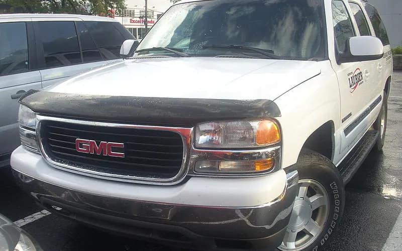
Common on this vehicle:Warning lightLoss of engine power, no accelerationLeakStalls or shuts offGauge or instrument faultMisfire or rough idleNoiseReduced braking
Record by record
10 records state a cause or a remedy. Each record is shown as short labels in the order fault → finding the cause → correction. Press a label to narrow to the records that state it.
Component named as the cause
Work done
How it is said to have ended
- says it held for a while3
- says it did not fix it4
- result not stated2
A ribbon is as wide as the records that state both of its ends (only the commonest are drawn). A record that names several symptoms or components runs through each. Orange is records that say the fault came back or was not fixed. Results come from owners’ reports only; one that does not say is “result not stated”. None of this is a likelihood of a cause or a rate at which work succeeds.
Read the records one by one (9)
Known issuesSingle-cylinder misfire (P0300-P0308) and/or chirp, squeak or tick at camshaft speed: worn cam lobe / lifter, valve or valve spring2
Manufacturer communication2000–2006 GMC YUKON XL ・ 2017-08-15
Engine Misfire and Service Engine Soon Lamp Information
1Fault
- With the SES light on, a P0300-P0308 DTC is found with misfires counting on a single cylinder, which may or may not be felt.
- The noise may be described as a chirp, squeak, squeal or tick and may increase off of idle.
2Finding the cause
- Valve Spring: broken
- Active Fuel Management Lifter: defective
- Valve: defective
- Camshaft Lobe: worn
- Lifter Roller: worn
Possible causes
- A worn cam lobe on this engine family generally makes a consistent chirp, squeak, squeal or tick at camshaft speed and/or a misfire with a P0300-P0308 DTC.
Steps to confirm (in the document’s order)
- Press on the rocker arms with a wooden hammer handle while the noise is present; if pressing the valve side of a rocker changes the noise, a lifter and/or cam lobe concern on that cylinder is most likely.
- Measure cam lobe lift at the push rod side of the rocker arm; it will differ from the SI specification but should be similar to the other rockers on the same bank.
- A bore scope or pen light may help when inspecting the cam lobes through the lifter bores.
- A good sign of a sticking valve is that misfires keep counting during an aggressive deceleration with engine braking.
- The Cylinder Leakage Test in SI should typically isolate valve leakage by showing excessive leakage past an intake or exhaust valve compared with the others.
3Correction
Repair
- If a worn cam lobe or lifter roller is found, replace the camshaft and all lifters per SI, plus the plastic lifter guide for the affected lifter (for the 2010 model year, all the plastic lifter guides).
- If force is needed to tap the valve off its seat, there is excessive carbon build up, which may be repaired by decarboning the engine.
Read the sentences of the record
From the manufacturer’s document
- Applies to:Applies to 1999-2013 GMC Savana, Sierra and Yukon (with a V8 engine per the model list) (note: the Yukon years run later than the years this service covers).
- Condition:With the SES light on, a P0300-P0308 DTC is found with misfires counting on a single cylinder, which may or may not be felt.
- Condition:The noise may be described as a chirp, squeak, squeal or tick and may increase off of idle.
- Cause:A worn cam lobe on this engine family generally makes a consistent chirp, squeak, squeal or tick at camshaft speed and/or a misfire with a P0300-P0308 DTC.
- Confirm:Press on the rocker arms with a wooden hammer handle while the noise is present; if pressing the valve side of a rocker changes the noise, a lifter and/or cam lobe concern on that cylinder is most likely.
- Confirm:Measure cam lobe lift at the push rod side of the rocker arm; it will differ from the SI specification but should be similar to the other rockers on the same bank.
- Confirm:A bore scope or pen light may help when inspecting the cam lobes through the lifter bores.
- Repair:If a worn cam lobe or lifter roller is found, replace the camshaft and all lifters per SI, plus the plastic lifter guide for the affected lifter (for the 2010 model year, all the plastic lifter guides).
- Confirm:A good sign of a sticking valve is that misfires keep counting during an aggressive deceleration with engine braking.
- Repair:If force is needed to tap the valve off its seat, there is excessive carbon build up, which may be repaired by decarboning the engine.
- Confirm:The Cylinder Leakage Test in SI should typically isolate valve leakage by showing excessive leakage past an intake or exhaust valve compared with the others.
- Confirm:The two pieces of a broken valve spring can stay stacked together and be hard to see, so lightly push on different places on the springs with a small hammer handle.
Open the manufacturer’s document (PDF) ↗ The points above were read from this document.
- Remedy
- This Preliminary Information communication provides information to the technician about vehicles that have a Service Engine Soon Malfunction Indicator Lamp on, engine misfire, and/or engine noise. Technician may find Diagnostic Trouble Codes P0300-P0308. If published Service Information diagnostics does not isolate the cause of this concern technician should check for a worn camshaft lobe and/or lifter roller, a sticking valve, valve leakage, a broken valve spring, and a collapsed active fuel management lifter.
Manufacturer communication2000–2006 GMC YUKON XL ・ 2017-08-15
Service Engine Soon Lamp and Engine Misfire Information
1Fault
2Finding the cause
3Correction
What the documents say to do
Single-cylinder misfire (P0300-P0308) and/or chirp, squeak or tick at camshaft speed: worn cam lobe / lifter, valve or valve springConfirm
- If pressing on the valve side of the rocker changes the noise, a lifter and/or cam lobe concern on that cylinder is most likely.
Repair
- If a worn camshaft lobe or lifter roller is found, follow SI procedures to replace the camshaft and all lifters.
- Also replace the plastic lifter guide for the lifter that had the damaged cam lobe and/or lifter roller.
Caution
- A damaged cam lobe is easy to overlook when inspecting through the lifter bores; unworn lifter rollers do not mean the cam lobes are okay.
Read the sentences of the record
Open the manufacturer’s document (PDF) ↗ What is shown here is NHTSA’s summary; the procedure is in the document itself.
- Remedy
- This Preliminary Information communication provides information to the technician about vehicles that have a Service Engine Soon Malfunction Indicator Lamp on, engine misfire, and/or engine noise. Technician may find Diagnostic Trouble Codes P0300-P0308. If published Service Information diagnostics does not isolate the cause of this concern technician should check for a worn camshaft lobe and/or lifter roller, a sticking valve, valve leakage, a broken valve spring, and a collapsed active fuel management lifter.
Known issuesReduced Engine Power from throttle body connector crimp, broken wire or grounds2
Owner complaint2003 GMC YUKON XL 1500 ・ 2015-09-28
1Fault
2Finding the cause
Not stated
3Correction
Read the sentences of the record
- Fault
- WHILE TRAVELING TO WORK MY VEHICLES CHECK ENGINE LIGHT CAME ON AND THE REDUCED POWER WARNING CAME ON AT WHICH TIME I HAD COMPLETE LOSS OF ACCELERATION, COMPLETE LOSS OF BRAKING, AND COMPLETE LOSS OF STEERING POWER. (1 more)
- Remedy
- I HAVE ALREADY REPLACED THE THROTTLE HOUSING AND HARNESS COMPONENTS, ACCELERATION PEDAL SENSOR AND YET THE ISSUE CONTINUES, SOMEONE IS GOING TO ( DIE ) BECAUSE OF GMC'S LACK OF CONCERN AND RESPONSIBILITY TO OWNERS OF THEIR PRODUCTS.
Owner complaint2003 GMC YUKON XL ・ 2010-09-04
ELECTRICAL SYSTEM4
Owner complaint2003 GMC YUKON XL ・ 2010-02-16
Vehicle stalls while in motion and when braking
1Fault
2Finding the cause
FIGURED OUT IT MAY BE RUNNING OUT OF GAS DUE TO THE GAUGE NOT WORKING.
3Correction
Read the sentences of the record
- Fault
- VEHICLE STALLS WHILE IN MOTION. (1 more)
- Cause
- FIGURED OUT IT MAY BE RUNNING OUT OF GAS DUE TO THE GAUGE NOT WORKING.
- Remedy
- REPLACED THE FUEL FILTER TWICE. (1 more)
Manufacturer communication2005–2006 GMC YUKON XL ・ 2018-06-04(1 earlier editions of this document folded here)
IP to Body Harness Connector Repair for MIL and DTC P2138
1Fault
- Loss of engine power, no acceleration
- Warning light
- Check engine / Service Engine Soon
- Reduced Engine Power
- P2138
- The engine warning lamp comes on intermittently with a message or indicator showing Reduced Engine Power.
- DTC P2138 (Accelerator Pedal Position (APP) Sensor 1-2 Correlation) is set as current or in history.
2Finding the cause
Possible causes
- Water may have entered the instrument panel (IP) to body harness connector, which carries the APP sensor signals to the ECM/PCM.
Steps to confirm (in the document’s order)
- Verify that no aftermarket equipment is electrically connected to the APP sensor signal or low reference circuits, or to any other ECM/PCM 5V reference or low reference circuit.
- Locate the IP to body harness connector, which may be in or around the left hand kick panel area or inside the IP.
- Inspect for a water leak in the area, using a water hose if necessary to find the source.
- Possible water leak points include the A-pillar seals, the sunroof drain lines (if equipped) and the windshield/cowl sealing.
- Inspect the terminals of the IP to body harness connector for corrosion and debris.
3Correction
Repair
- If a water leak is found, repair it as necessary and verify that the repair is effective.
- If corrosion or debris is found on the connector terminals, repair as necessary.
Caution
- Aftermarket equipment can generate DTC P2138 and/or other DTCs.
Read the sentences of the record
From the manufacturer’s document
- Applies to:Applies to 2018 and prior GM passenger cars and light duty trucks.
- Condition:The engine warning lamp comes on intermittently with a message or indicator showing Reduced Engine Power.
- Condition:DTC P2138 (Accelerator Pedal Position (APP) Sensor 1-2 Correlation) is set as current or in history.
- Cause:Water may have entered the instrument panel (IP) to body harness connector, which carries the APP sensor signals to the ECM/PCM.
- Caution:Aftermarket equipment can generate DTC P2138 and/or other DTCs.
- Confirm:Verify that no aftermarket equipment is electrically connected to the APP sensor signal or low reference circuits, or to any other ECM/PCM 5V reference or low reference circuit.
- Confirm:Locate the IP to body harness connector, which may be in or around the left hand kick panel area or inside the IP.
- Confirm:Inspect for a water leak in the area, using a water hose if necessary to find the source.
- Confirm:Possible water leak points include the A-pillar seals, the sunroof drain lines (if equipped) and the windshield/cowl sealing.
- Repair:If a water leak is found, repair it as necessary and verify that the repair is effective.
- Confirm:Inspect the terminals of the IP to body harness connector for corrosion and debris.
- Repair:If corrosion or debris is found on the connector terminals, repair as necessary.
Open the manufacturer’s document (PDF) ↗ The points above were read from this document.
- Remedy
- This technical bulletin provides repair information for repairing the IP to body harness connector to correct a customer concern for intermittent Malfunction Indicator Lamp (MIL) illuminated with Reduced Engine Power displayed and DTC P2138 set.
Manufacturer communication2005 GMC YUKON XL ・ 2018-05-21
Throttle Position Sensor Cover Replacement
1Fault
- Loss of engine power, no acceleration
- Warning light
- Check engine / Service Engine Soon
- Reduced Engine Power
- P2135
- P1516
- P2101
- P2176
- The malfunction indicator lamp (MIL) is illuminated with a Reduced Engine Power message displayed.
- A scan tool may show DTC P2135: Throttle Position (TP) Sensor 1-2 Correlation set as Current or in History.
2Finding the cause
Possible causes
- The condition may be caused by the difference between TP Sensor 1 and TP Sensor 2 exceeding a calibrated value for more than 2 seconds.
Steps to confirm (in the document’s order)
- After installing the new cover, if the scan tool TP Sensor 1 and 2 Agree/Disagree parameter displays Disagree, replace the throttle body assembly.
- If DTC P1516, P2101 and/or P2176 are set, replace the throttle body.
3Correction
Repair
- Clean the throttle body bore and throttle plate with a clean shop towel and GM Top Engine Cleaner, P/N 1052626 (in Canada, P/N 993026), or ACDelco Upper Engine and Fuel Injector Cleaner, P/N 88861803, or an equivalent product.
- Remove the old TP sensor cover from the throttle body: grasp the cover, carefully lift it up and separate it from the throttle body.
- Tighten the throttle body fasteners to 89 lb in (= 10.1 N·m) (the text prints the metric value as "10 Y").
- Reprogram the ECM using the Service Programming System (SPS) with the latest calibration available on TIS2WEB.
- Perform the Throttle Learn Reset Procedure.
Part numbers printed in the document
88861803Cleaner,Fuel Injector & Upper Engine Acdelco 16OzLook up at RockAuto (aftermarket candidates) ↗Search the web ↗
Replaced by: 19355198as stated by GMPartsGiant (checked 2026-10-06) ↗Look up at RockAuto (aftermarket candidates) ↗Search the web ↗
The numbers are as the document prints them. The name and the replacing number are what the pages of GMPartsGiant, a reseller of genuine parts and not GM, state. Aftermarket equivalents are not checked here (the links only search by number). Confirm the fit for the vehicle (VIN) before ordering.
Parts
- Part number 19259452, Throttle Position (TP) Sensor Cover, quantity 1.
Part numbers printed in the document
19259452Sensor Kit,Throttle PositionLook up at RockAuto (aftermarket candidates) ↗Search the web ↗
No successor statedas stated by GMPartsGiant (checked 2026-10-06) ↗
The numbers are as the document prints them. The name and the replacing number are what the pages of GMPartsGiant, a reseller of genuine parts and not GM, state. Aftermarket equivalents are not checked here (the links only search by number). Confirm the fit for the vehicle (VIN) before ordering.
Caution
- Do not replace the throttle body; follow the procedure in the bulletin instead.
- If the throttle body is dropped at any time during the procedure, abort the procedure and replace it with a new throttle body assembly.
Read the sentences of the record
From the manufacturer’s document
- Applies to:The Yukon entries are 2008-2011 GMC Canyon, Savana, Sierra, Sierra Denali and Yukon models (note: earlier Yukon model years are not listed).
- Condition:The malfunction indicator lamp (MIL) is illuminated with a Reduced Engine Power message displayed.
- Condition:A scan tool may show DTC P2135: Throttle Position (TP) Sensor 1-2 Correlation set as Current or in History.
- Cause:The condition may be caused by the difference between TP Sensor 1 and TP Sensor 2 exceeding a calibrated value for more than 2 seconds.
- Caution:Do not replace the throttle body; follow the procedure in the bulletin instead.
- Repair:Clean the throttle body bore and throttle plate with a clean shop towel and GM Top Engine Cleaner, P/N 1052626 (in Canada, P/N 993026), or ACDelco Upper Engine and Fuel Injector Cleaner, P/N 88861803, or an equivalent product.
- Repair:Remove the old TP sensor cover from the throttle body: grasp the cover, carefully lift it up and separate it from the throttle body.
- Caution:If the throttle body is dropped at any time during the procedure, abort the procedure and replace it with a new throttle body assembly.
- Confirm:After installing the new cover, if the scan tool TP Sensor 1 and 2 Agree/Disagree parameter displays Disagree, replace the throttle body assembly.
- Confirm:If DTC P1516, P2101 and/or P2176 are set, replace the throttle body.
- Repair:Tighten the throttle body fasteners to 89 lb in (= 10.1 N·m) (the text prints the metric value as "10 Y").
- Repair:Reprogram the ECM using the Service Programming System (SPS) with the latest calibration available on TIS2WEB.
- Repair:Perform the Throttle Learn Reset Procedure.
- Parts:Part number 19259452, Throttle Position (TP) Sensor Cover, quantity 1.
Open the manufacturer’s document (PDF) ↗ The points above were read from this document.
- Remedy
- This technical bulletin provides a procedure for replacing the throttle position sensor cover for concerns regarding a indicator lamp illuminated reduced power message displayed and DTC P2135 set.
Owner complaint2005 GMC YUKON DENALI XL ・ 2015-08-31
Speedometer erratic reading and cruise control malfunction on highway
1Fault
2Finding the cause
3Correction
Read the sentences of the record
- Fault
- WHILE DRIVING ON THE HIGHWAY WITH MY CRUISE CONTROL SET BETWEEN 50-70MPH (= 80.5–112.7 km/h), I BEGAN NOTICING MY SPEEDOMETER BEGINNING TO JUMP BETWEEN 0-120MPH (= 0–193.1 km/h) CAUSING THE LIMITER TO KICK IN AND ME LOSING THE ABILITY TO CONTROL SPEED. (4 more)
- Cause
- SOME HAD SIMILAR ISSUES AND SAID THE IGNITION COILS MAY BE BAD.
- Inspection
- I WAS TOLD THAT I HAD A BAD MASS AIR FLOW SENSOR. (1 more)
ELECTRICAL1
Recall2000–2001 GMC YUKON XL ・ 2005-04-15
Fuel Module Reservoir Assembly Overheating Recall
1Fault
2Finding the cause
3Correction
Not stated
Read the sentences of the record
- Cause
- Certain vehicles were built with fuel module reservoir assemblies that contain fuel pump wires and/or connectors that may overheat under certain operating conditions. Fuel pump wires that overheat may become exposed and result in one or more conditions; 1) If the ignition circuit wire is exposed and shorts to ground, the fuel pump fuse will blow, disabling the fuel pump and causing an engine stall or no-start condition. 2) If sufficient heat is conducted to the pass-through connector, a hole in the connector may result, which may cause the Service Engine Soon light to be illuminated during the emission system diagnostics routine. Fuel vapour (and in some limited cases liquid fuel) may leak out of the fuel tank through the hole in the connector body. 3) If the ignition circuit or ground wire is exposed and shorts to the fuel level sender card wires, inaccurate fuel level readings may result. Correction: Dealers will affect repairs.
Showing 9 of the 10 you can open. Narrow the search to see the rest.
1 owner complaints have no classified sentences yet, so their causes and repairs are not picked out. Their text is in the list of records.